

![]()
16/07/08
I've spoken to Ali at Stingray Motorsport and the kit should be ready for collection around the 1st of August... <gulp>
I've ordered:
- Chassis kit (no bodywork yet to keep costs down and save space)
- Powdercoating in satin black
- Protech shocks
- Alloy steering rack clamps
- Fuel tank
- Steering colum lower link
- Steeering column bush
- Brake lines
- Braided hoses
- Tandem master cylinder
I've also got Stingray to cut and shape (but not fit) the larger aluminium panels for me since I am just not set up to do a good job of this (IMHO) and these are highly visible on the finished vehicle. I know it goes against my whole ethos of doing everything myself and the whole 'sense of ownership' thing, but I didn't want to see a wiggly jigsaw cut line every time I jumped into the Mojo!
![]()
Day off work - up early - about as excited as a kid on Christmas day...
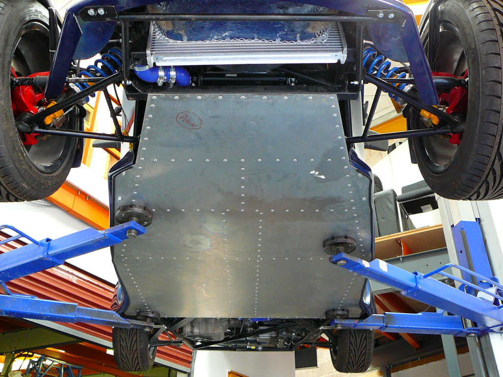
Pick up the van at 8:30am and head off towards Stingray with a thermos of hot coffee and a pair of rusty Capri uprights. Eventually worked out how to turn the stereo on and found Radio 2. Arrived at 12:00. Spent some time with Alistair going through the kit and making sure we had everything (which it turns out we don't, but that's later...) and loaded everything into the van. Also had a good oppurtunity to look at a Riot and a Mojo while I was there. The Mojo was up on the ramps at the time so out came the camera and a few reference shots were taken.
Made it back to Suffolk around 6pm, and promptly enlisted the help of my wife and my housemate to help me unload the chassis onto the eagerly awaiting build stands.
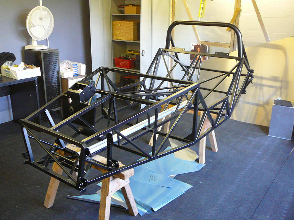
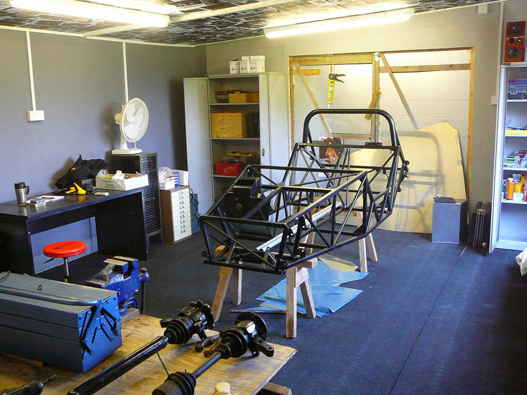
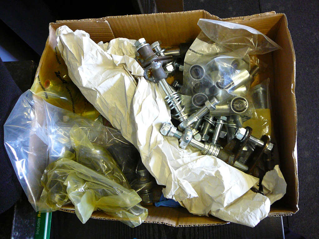
After an unhealthy amount of coffee, I sat down to start checking over the bit list and to make sure I knew where everything went. As you can see, most of the fixings have arrived in a large box of assorted items, but it's fairly obvious where most of them go (although the build manual was consulted several times!).
It transpires that everything is here except for the lower steering link which was still glowing red hot on Ali's bench at Stingray when I left as he was still doing some welding on it. Hopefully that'll arrive in the next day or two. Also missing are the two alloy steering rack clamps, but I don't need them just yet so I'll add them to the list of things to talk to Alistair about when he gets back from holiday. Also noted that the brake master cylinder has different mounting holes, has a black opaque resevoir, and does not have any form of level switch. Hmmm.... maybe not SVA compliant then? Added to the list.
![]()
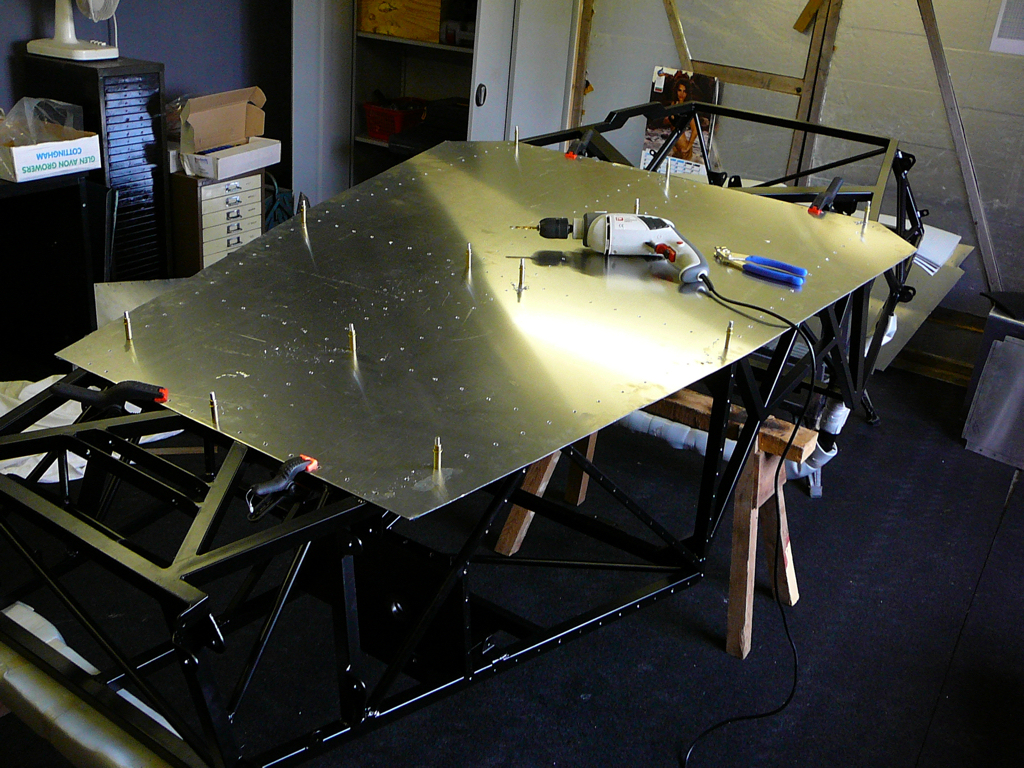
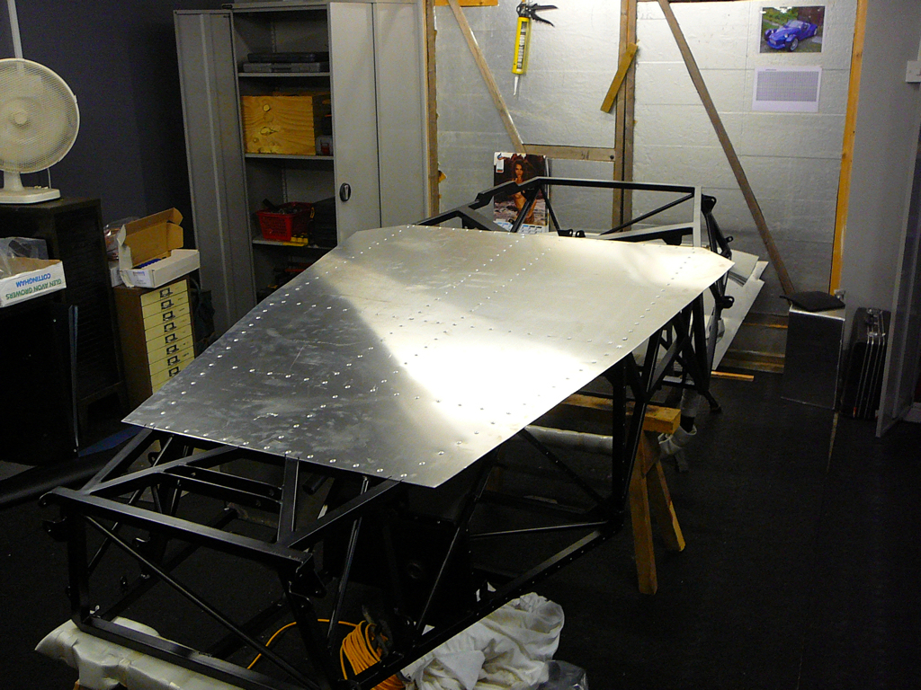
The first job today is to go through all of the aluminium panels and trim them to size. Now I must admit that I have cheated a little here, and I got Stingray to do the initial cutting for me, so I collected a set of (nearly) shaped panels and a large box of offcuts. A bit of fitting, marking, cutting and checking has resulted in most of the panels now being ready to fit. I just need to wait for my Cleko kit to arrive from my favourite shop (eBay) and I'll be able to start fitting them.
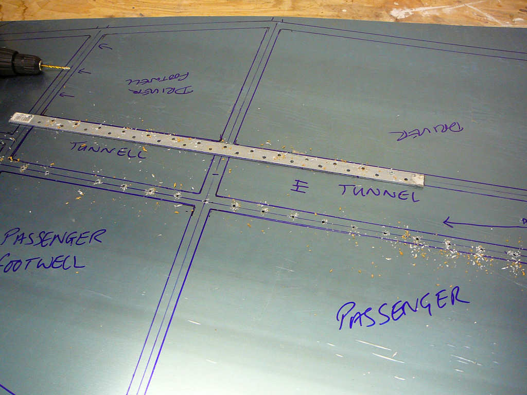
For now, I've drilled the floor panel. The chassis was laid on top of the bare panel on the floor and lines were drawn around the chassis tubes. With the floor panel back on the bench, the centres of these tubes were marked and 4.8mm holes drilled at 50mm centres. I know the build manual says 40mm (what do you mean you haven't read it??!) but some calculations show that 50mm is more than adequate on 1.5mm aluminium plate. I used a length of steel with 50mm spaced holes to help with the drilling which should result in nice straight lines. Previously, I've found that even with a dot punch, the final location of a drill point is always somewhat variable!
![]()
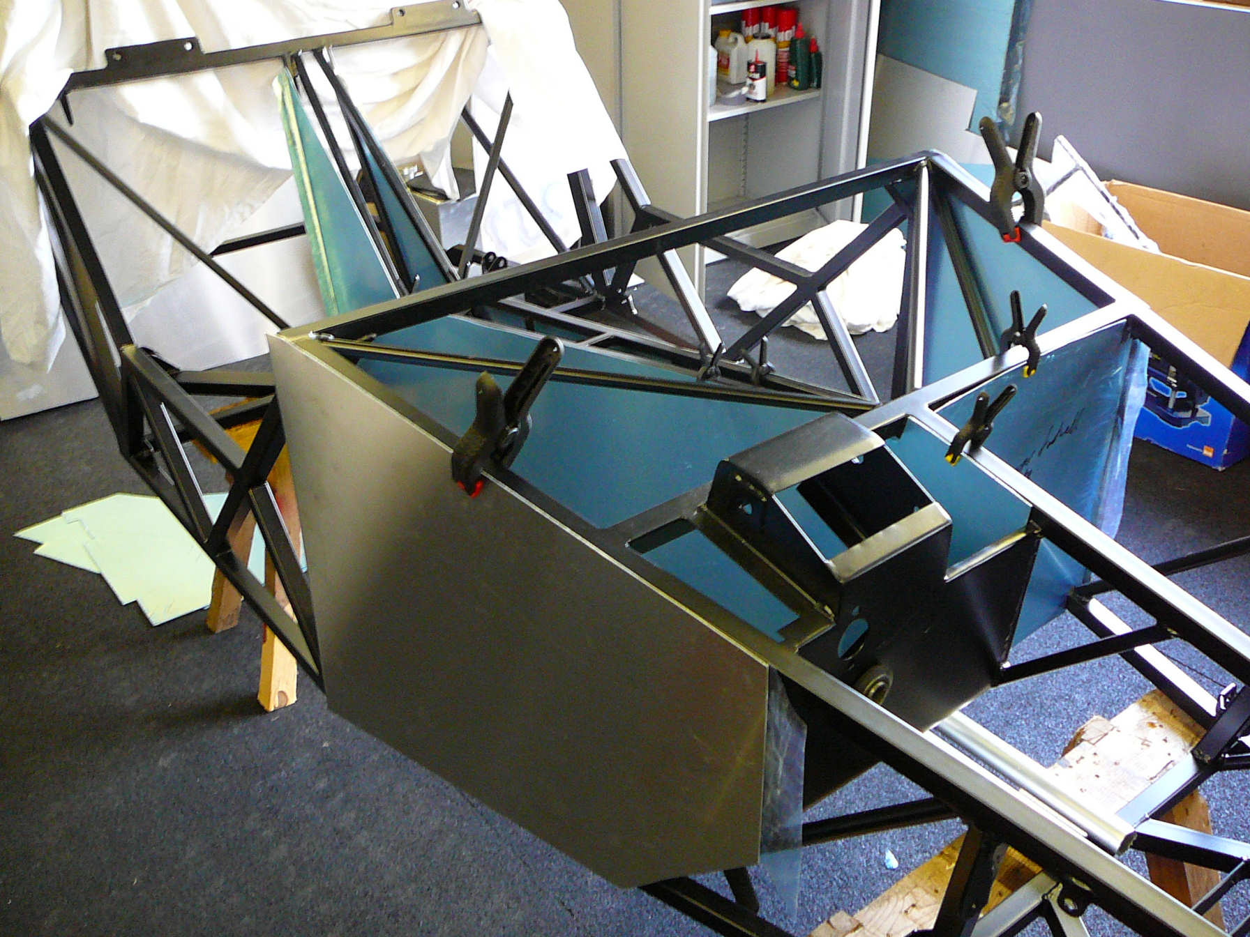
I had to do it... my wife and I sat in the chassis today while it was on the floor and tried it out for size. After a couple of imaginary laps of Snetterton, we pulled into the pretend pits, and switched off the non-existent engine. Oh well... back to work. Note: No one made any vroom vroom noises. Honestly.
More panelling preparation. Re-worked a couple of the bends that had been put into the panels so that they fit better.
Also started to dry-assemble the suspension to help identify some of the more obscure parts. It turns out that the powder coater hasn't worried about masking any of the threads so they're all filled with powder coat now. I'll leave that until I get some idea of how to proceed. Also decided to let a local garage fit the metalastic bushes because they really are as tight as you hope they aren't, if not slightly tighter!
![]()
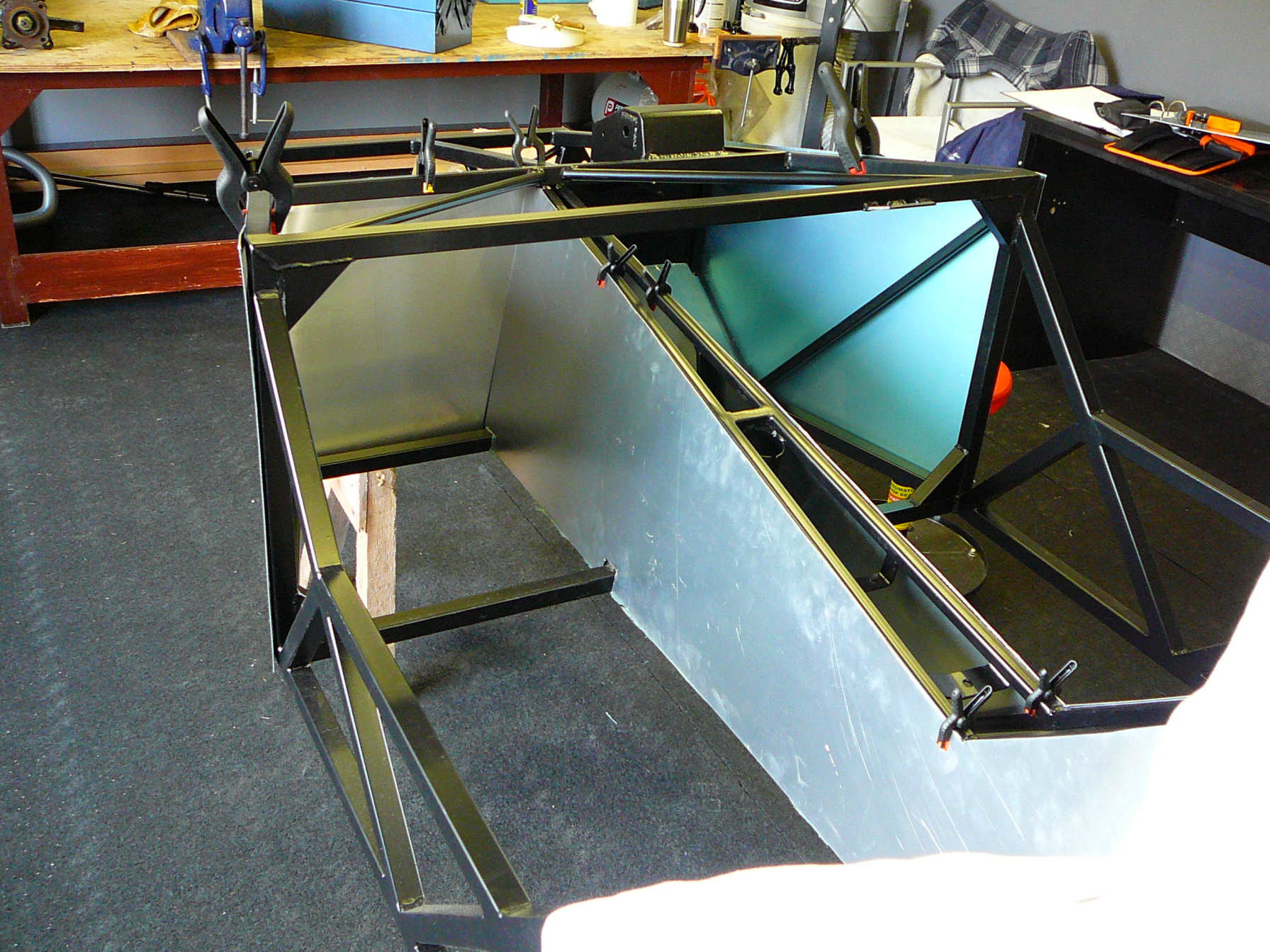
More panelling, but with the aid of clekos now, which make life much easier!
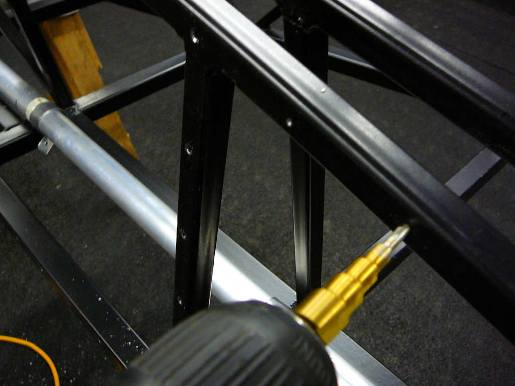
The step drill is very useful, and makes relatively light work of drilling the steel chassis. Because it has straight flutes, it doesn't grab the material at the end of the hole, and it is also much stronger than standard twist drills. It'll go blunt before it breaks! I'm glad I bought 3 of them...
Here's the procedure I've ended up using when drilling panels:
- Fit the panel to the chassis using spring clamps.
- Mark any parts that need trimming.
- Remove from chassis and trim to fit using aviation snips.
- Repeat until it all looks ok. (Remember to leave a gap around the panel to allow for the folded over edge of any vinyl trim etc!)
- File and sand the edges of the panel, and round off the corners.
- Refit the panel using spring clips and align carefully.
- Use a permanent maker and mark around all of the chassis tubes on the reverse side of the panel.
- Remove the panel and lay it on the bench. Using whichever arrangement of measuring tools you find most appropriate, mark the centreline of each of the tube locations on the panel.
- Spend some time laying out the rivet locations along these centrelines. These will be visible in the finished car, so take time here!
- Check that all of the holes in the chassis that correspond to a rivet hole you just marked can actually be reached by a drill, and that it's not right on a weld etc.
- Dot punch the rivet locations on the aluminium panel.
- Check - last chance....
- Drill the aluminium panel.
- Deburr both sides.
- Fit the panel to the chassis and check each hole to make sure it's ok.
- Using the aluminium panel as a guide, carefully drill a hole into the chassis.
- Fit a cleko to hold the panel in place.
- Drill more holes and fit clekos to ensure that the panel is securely held. I find that 2 or 3 are enough for most panels, but the tunnels require a few more since they are significantly larger.
- Using the tip of the step drill, mark the location of each hole. Only drill to a depth of 1-2mm.
- Remove the aluminium panel and check that the hole marks are roughly central in the tubes.
- Put Pink Floyd on the headphones, get comfortable, and drill out all of the holes. The step drill makes a good job of these, and also deburrs them as it goes through. I found that I can do about 20 holes before the bit gets too hot to work effectively (even with cutting fluid) so I keep another bit in another drill and swap ever now and again.
- Finally, refit the panel using clekos and check that everything lines up ok.
- Take a break and get ready for the next one...
I know that this sounds like a fairly long process and it is quite tedious, but I have found that it gives the best quality finish and that's what is imoprtant after all!
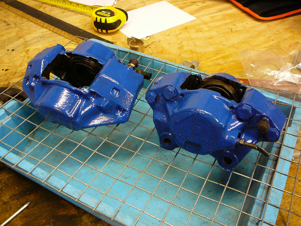
In between panels, I'm also doing some odd jobs for variety, and for when drilling into steel is considered anti-social (apparantely, some people may not appreciate drilling and hammering at 2am. Go figure...) So, last night, I put the first coat of caliper paint onto the front brakes. This is after they have been shot-blasted, and treated with Kurust anti-rust fluid. I'll let this set for a day or so and then apply the next 3 coats. Hopefully this means that it won't flake off like you see on some of the horrors on barryboys.co.uk.
The lower steering link arrived from Stingray this morning. I quickly checked it would fit and then put it on the shelf with the other steering bits. It's too much of a distraction to be playing with 'bits that move' while I'm doing panelling!
Thanks also to Neil Everett for putting a link to this site on www.mymojo.co.uk.
Also sent off the Sierra brakes to Bigg Red for refurbishment. It's been a busy couple of days!
![]()
Popped into the local garage this morning to drop off the suspension arms to have the metalastic bushes fitted.
A few minutes and a 15-ton hydraulic press later - and voila! Thankyou to Nigel at Stowupland FastFit - it's easy when you've got the right tools.
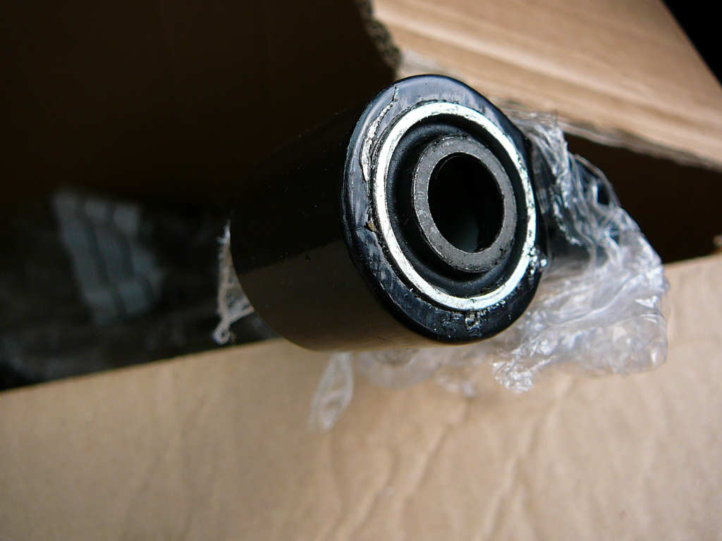
One thing I noticed is that I've only got 14 bushes. This completes the suspension arms, but there are another 4 required for the engine mounts. Another thing to add to the 'Ask Alistair' list.
![]()
Its been a busy few days recently...
Firstly - the mammoth drilling session has come to an end (for now) and the vast majority of the holes required in the chassis are complete. The total so far is around 570 holes, with no drill breakages (apart from one cordless drill which now refuses to run at full speed...)
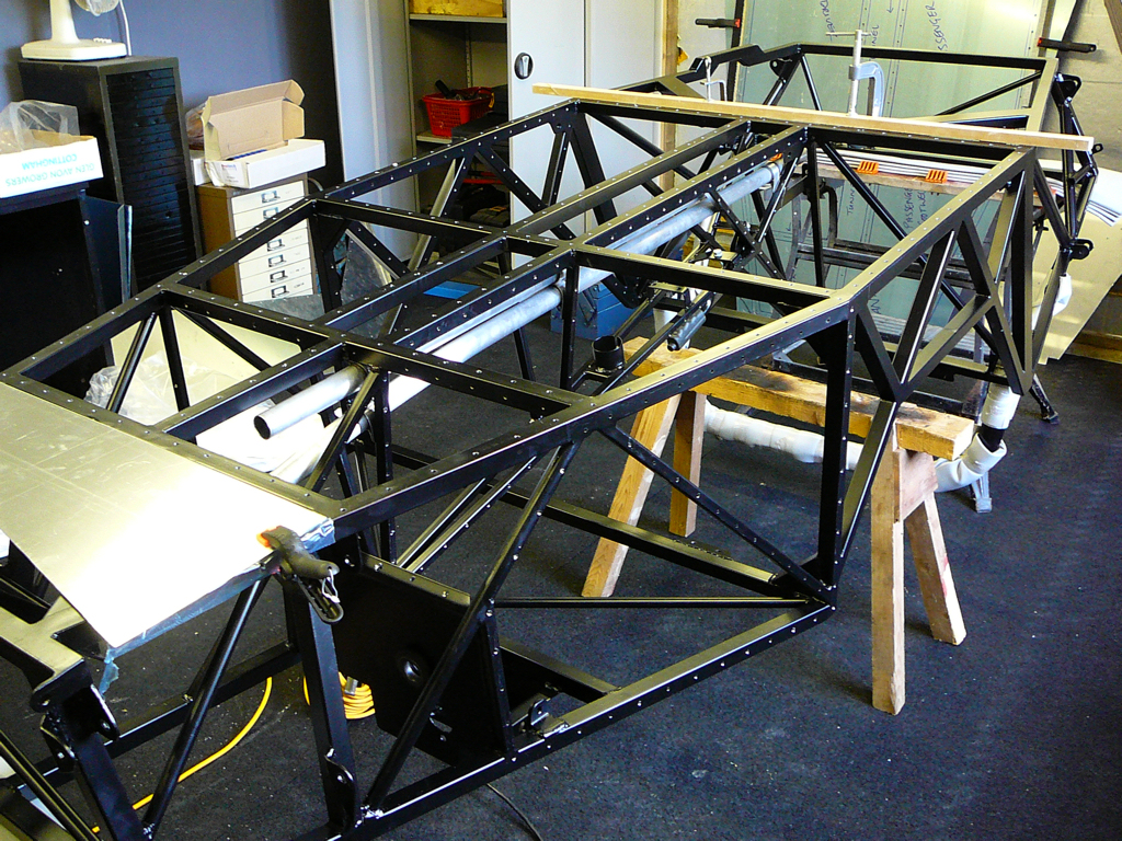
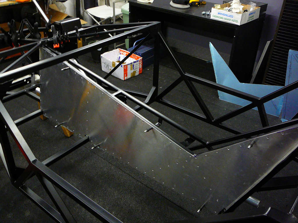
The next step was to apply some Tiger Seal PU adhesive, then carefully lower the floor into place. This floor has to be placed accurately since any movement will just smear the adhesive across the floorpan. For this reason, I enlisted the help of my ever patient wife who helped to make the job very easy. Some clamps were used to hold the floor in the correct place, and all 173 rivets were fitted into the holes. It was then a matter of going around each rivet with the lazy tongs and popping them into place.
Tip: Start rivetting at the centre and work outwards to prevent ripples appearing in the floor..!
25 minutes later, it was finished and a celebratory coffee was thoroughly enjoyed.
The adhesive was given an hour or so to go off before the chassis got flipped over again. Now we can start fitting suspension... but thats for next week.
Also over the last few days (well, late nights/early mornings to be precise), I've been doing some more of the 'little' jobs.. A top tip came from our Engineering Manager at work (thanks Dickie!) who when asked about clearing powdercoat from threads, simply said 'Nitromors' and grinned. Seeing as it was also his suggestion to use a step drill instead of standard HSS bits, I thought OK, I'll give it a go... Dab a glob of the stuff into the thread using a cotton bud, wait 5 minutes, remove gloopy paint and miscellaneous grot with more cotton buds. Easy! Specifically, this was needed on the threads for the top balljoints on the front uprights, and the brake mountings on the front hubs. A little copper grease to ease the way and the job was complete. Ok, so the top ball joints needed to be clamped in a vice and a big pair of Stilsons used to put the final turn on them, but these things are holding on the front wheels so they need to be tight! Finally, the large lock washer was tapped over and they were put to one side.
I dry fitted the front suspension and steering to make sure everything lines up ok - which is not very easy when you don't have steering rack clamps. Nevertheless, the suspension arms all fitted perfectly, and the 12" Protech shocks look great.
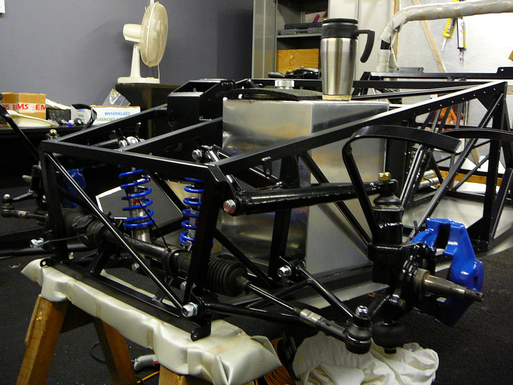
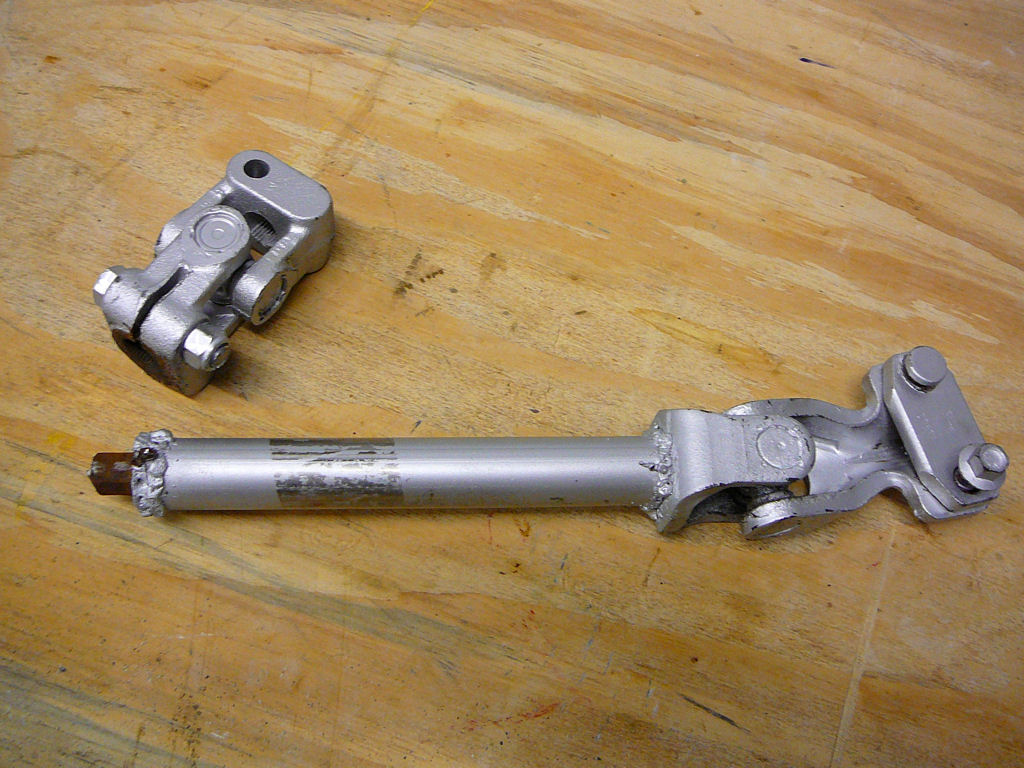
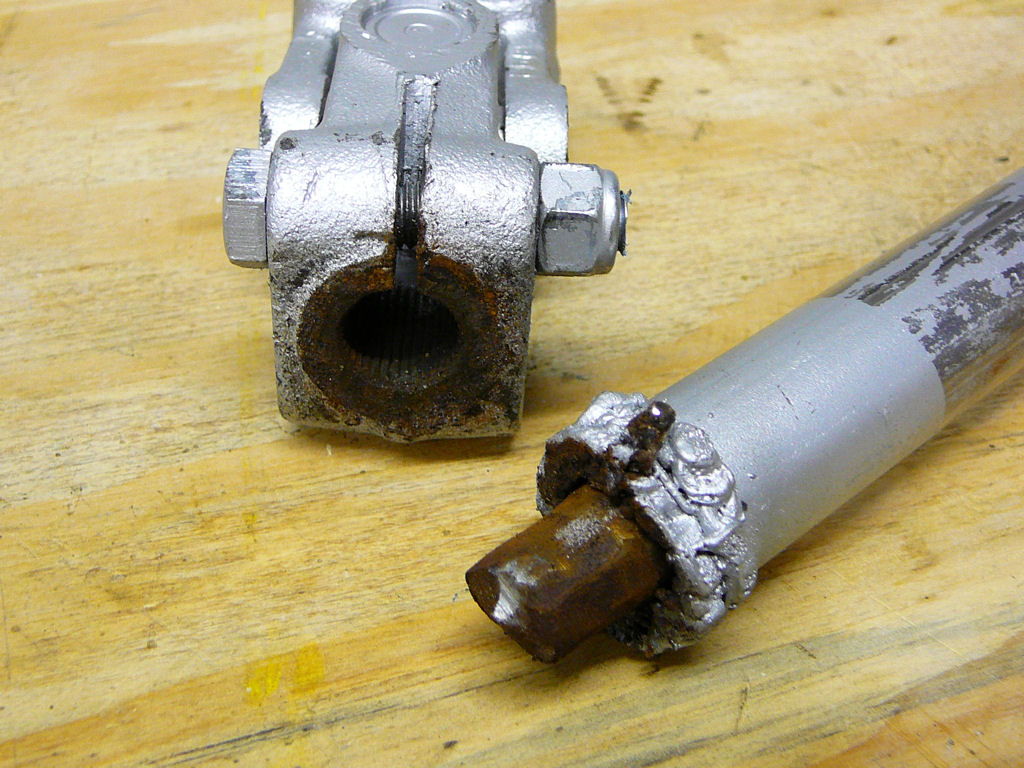
Unfortunately, the lower steering extension supplied by Stingray is too long so it needs to go back for rework and I also had doubts about the welding on this piece as it didn't look like there was much penetration (or any in fact). While investigating, one of the welds broke and the thing fell apart. Glad it didn't do that to me on a roundabout one morning! Added to the list.
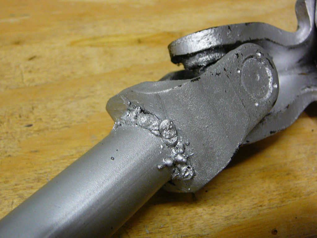
Update: 020908
It turns out that the steering link shown above is in fact the Stingray in-house mockup which gets used as a jig for the Riot, and it got posted to me by mistake. I'll post some pictures of the new link when it arrives...
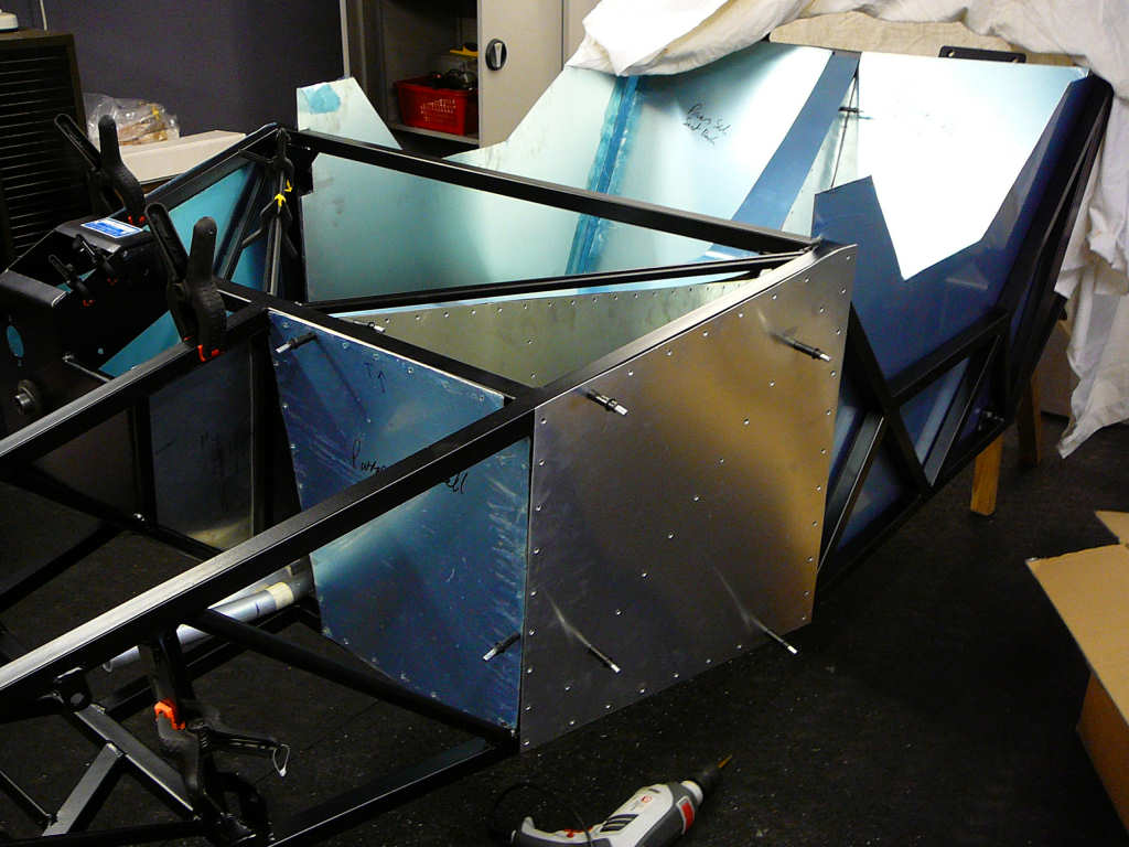
I've also covered the cockpit panels with black vinyl. This both looks better than bare aluminium (IMHO) and should help the SVA 'sharp edges' test. Most of these panels won't be fitted for some time in order to leave good access in the tunnel and pedal box, so they've been safely tucked away for now.
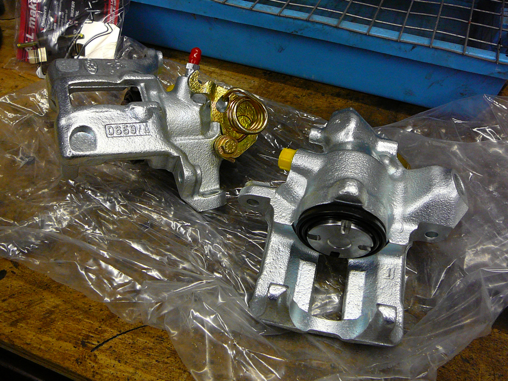
The Sierra calipers have come back from Bigg Red and now they are all shiny and new. I also got new spring clips for the both the Sierra and Capri calipers. Great service from these people!
The other main task this weekend was to start work on the Fiesta. Up to now, this as been left complete as I didn't want to take something off before I needed it, only to forget where I'd put it! Also during this process, I'm trying to get to grips with the Ford PATS immobiliser system. When I was speaking to Jeremy Philips at Sylva last week, he said that he is also trying to use a Ford ECU on a Zetec 1.25 engine but could not get the engine to turn over. Being an electronics engineer and fearing that this may be an omen for my build, I started asking some questions and eventually offered to see what I could do to help. Therefore, the first step was to remove the dashboard and expose the wiring which leaves us with this...
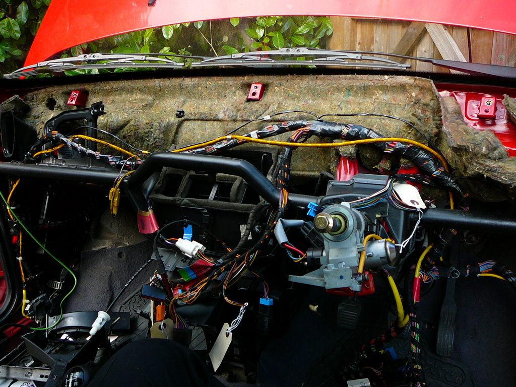
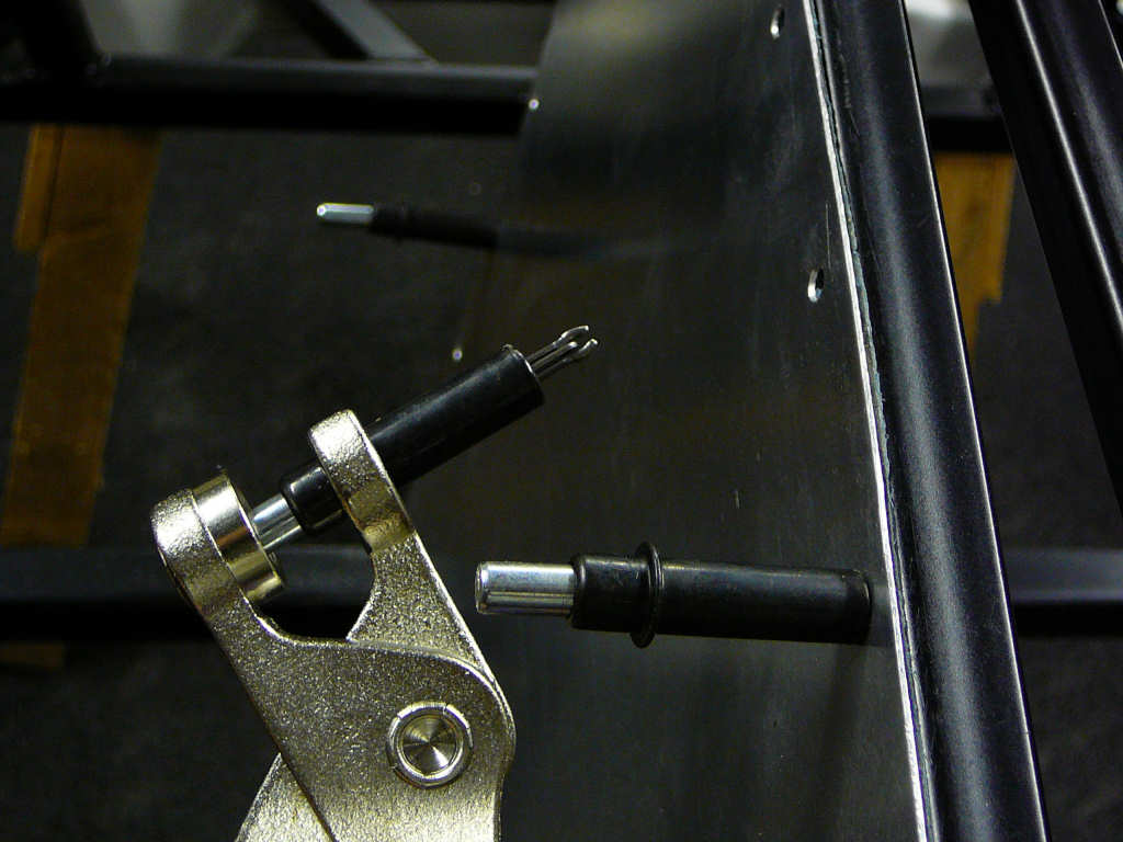
Removing the airbag was a little unnerving, but now its out. It was suggested that we launch it into a bonfire from my Trebuchet and see what happens. Hmmm... maybe not eh? For now it's in a box with appropriate warnings on it. Anyway - the wiring is now exposed and the combination of Haynes manual and Ford TIS DVD has enabled me to at least identify where all of the control modules are and what they should do. The first thing JP wanted me to check was related to the transponder in the keyfob. There is a receiver unit which fits around the ignition barrel and I was asked to see if this worked ok when removed from the steering column. Therefore, I removed the unit and held it away from the column behind the key, and tried to start the engine. First turn and the engine fired! So I moved the receiver slightly further away and tried again... The tall and short of it is that the receiver can be up to an inch or so away from the fob but must be perpendicular to the key. I'llbe coming back to this later at things develop...
![]()
Spent some more time sorting through Fiesta wiring.So far it's a case of labelling every single connection and taking photos. I'm compiling these into a PDF file as I go so I'll put it on the site when it's finished. It turns out that my donor Fiesta doesn't have any form of alarm fitted which makes the wiring somewhat simpler. The immobiliser is still present and will need to be moved to the Mojo, but this is just a case of using the PATs transceiver (which is around the ignition key) and the powertrain module (ECU) which I'll use anyway since it saves me around £650 for an Emerald ECU. Some later Fiestas appear to have an additional device inside the instrument cluster that will also inhibit ignition if it is missing - thankfully this is not used in mine!
The 5/16" copper pipe has arrived for the fuel lines along with some rubber lined P-clips which I'll fit later.
I've removed the pedals from the Fiesta and the brake pedal is ready to go off to JP for modification. I've test fitted them into the chassis and so far everything seems to fit. I also removed the front brake disks from the Fiesta since they were nearly brand new. Unfortunately, they're too big which is a bit odd since the build manual states 'The rear brakes use the solid front disks from the smaller engined Fiestas'. I thought that the 1.25 was a small engine but no - it should actually read something like 'the rear brakes use the 221mm solid front disks from a MK2 Fiesta (not XR2)'.
I've ordered the brake disks from my local Motorspares, along with 4 new CV boots.
Started to fit the copper brake lines which were made by Stingray and I've run into some problems. Namely, the long pipe for the tunnel is too long (by around 300mm), and the two rear pipes are different lengths. One seems ok, but the other is about 350mm short. Also, it look slike I've got the wrong nut/t-piece combination so the brass nut bottoms out inside the t-pieces before the copper is swaged. With the brass nuts done up tight, there's still around 2-3mm of movement in the copper pipe.
![]()