


![]()
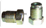
Continuing the brake pipe story from last month: The nuts fitted to my brake lines are fully threaded, whereas the t-pieces have an unthreaded portion at the bottom meaning that they are supposed to be used with the part-threaded unions.
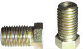
Looking at www.brake-pipes.co.uk, it seems that the full thread unions are often used on Japanese cars, whereas the part thread ones are used on british cars. I've spoken to Ali at Stingray and he's going to sort it out for me, along with a replacement steering link and my steering rack clamps.
I've collected the brakes disks and CV boots from Motorspares which should allow me to modify the Sierra brake mounts to fit correctly. Only problem is that there is a tiny lip inside the disk where the hub seats, and the hub is approximately 1mm larger diameter than this lip meaning that the disk doesn't seat fully. 5 minutes later with an angle grinder and they fit. I just took off a small amount of material all around the edge of the hub flange until the disks fitted.
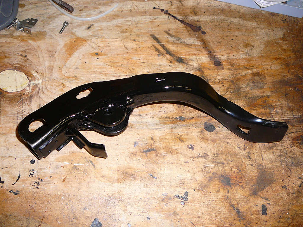
Also shipped the brake pedal off to Jeremy for modification.
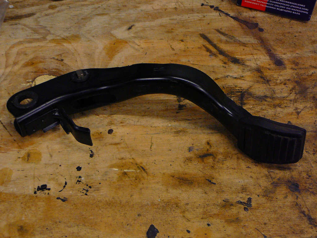
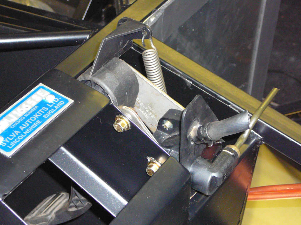
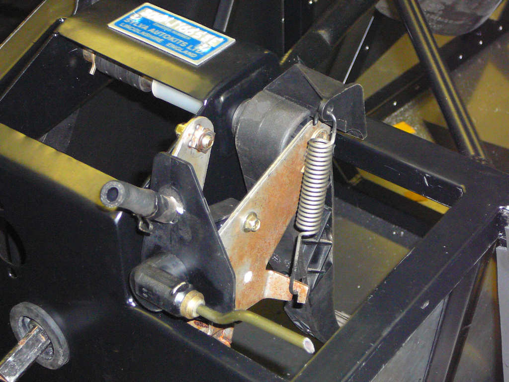
I took some quick photos of the pedal arrangement for reference:
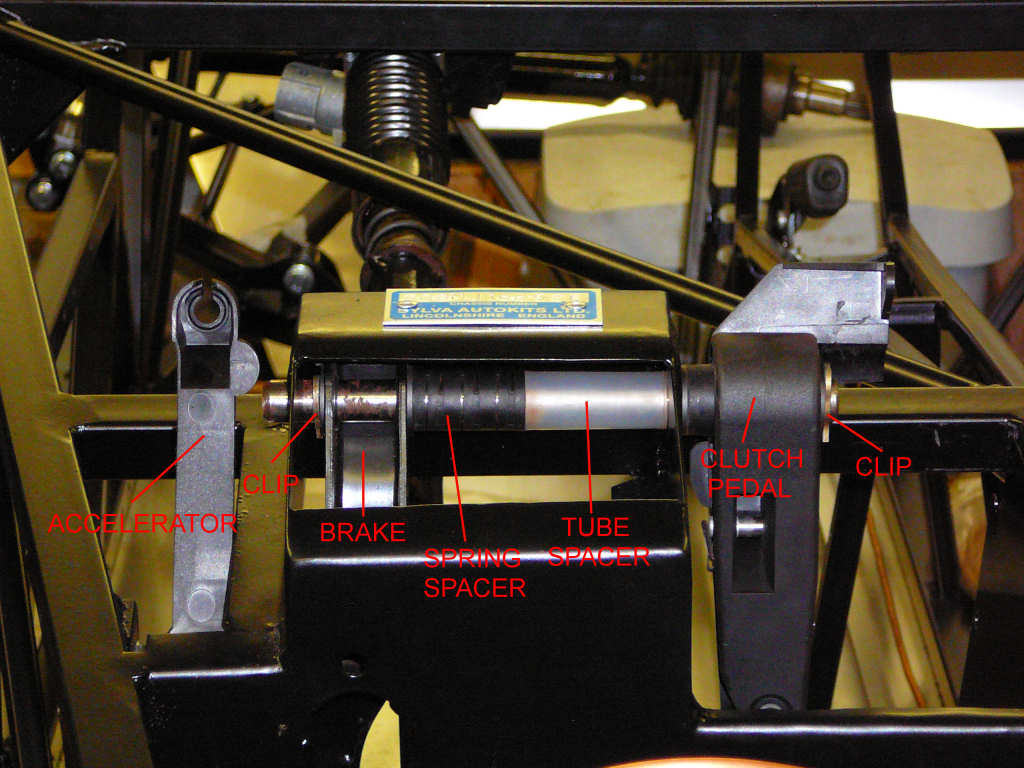
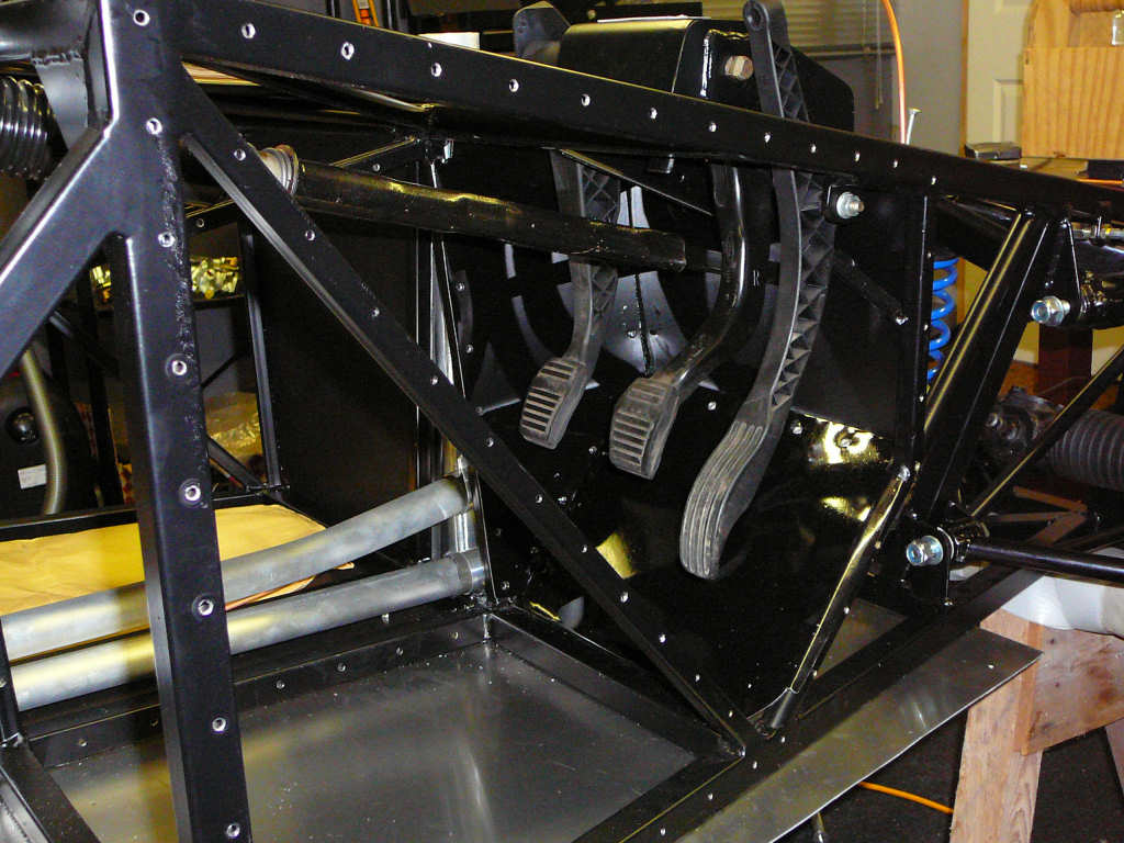
All of the pedal components just slot into place with no modifications required (apart from the brake pedal) so ignore what it says in the build manual about cutting down tube spacers! Also cut the copper fuel lines last night - approx 8 feet long each. These are currently rough-fitted into position awaiting permanent fixing.
![]()
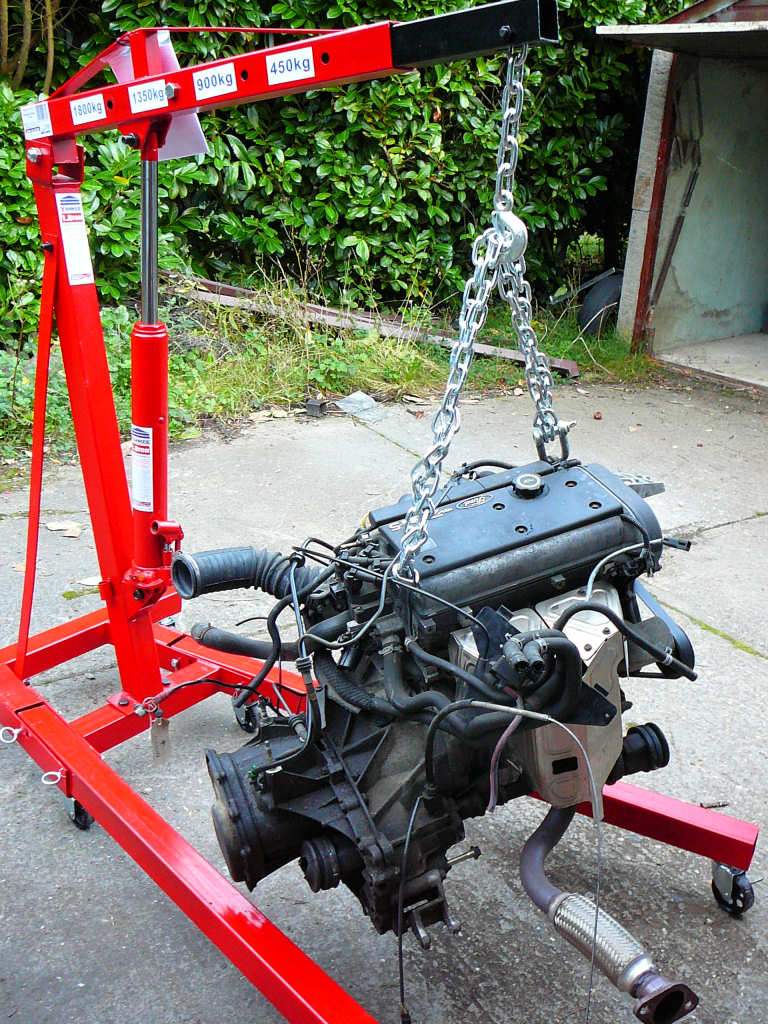
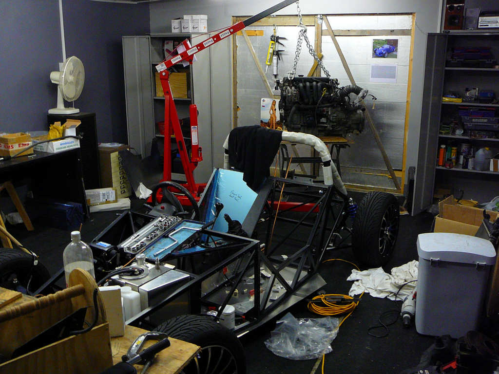
Collected a new 1.8 ton engine crane today. A bit overkill for a 1.25L engine made of aluminium, but it made sense to get one (and it's another big red shiny toy!)
<ahem>
Two jobs done tonight - brake mounts for the rear brakes, and steering column.
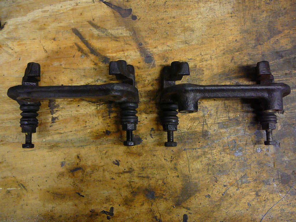
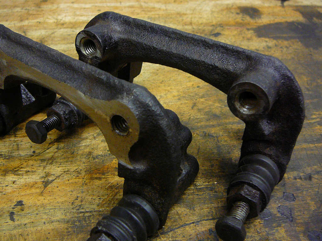
Here are some before and after shots of the modifications required to the Sierra brake mounting brackets. I ended up removing 15mm of material in order to centre the disk as shown below. I did the rough cuts with a hacksaw (this material is much softer than the steering arms!) and did the fine finishing with an angle grinder and a file. One thing I did learn is that el-cheapo hacksaw blades are absolutely useless! I had a pack of 10 cheap-and-nasty blades and I wore the teeth off of two of them doing just one cut, then I put the old (better but blunter) blade back on and it did the other three cuts without hesitation. One day I'll learn.... one day...
After many 'trim, try, repeat' cycles - I was done and the brackets were put to one side to be painted. I save painting for one of my late-night jobs for when angle grinders are too noisy and muscles are too sore!
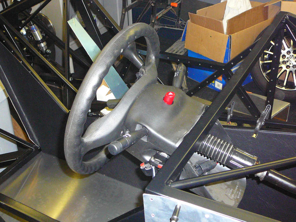
Over the past few weeks I've had a set of Sierra steering column switchgear sitting up on a shelf in the workshop, and I keep looking at it and thinking 'do I want that in my car?'. It's a bit old-fashioned looking in my opinion, but I still think that it would be better to use column switches rather than dashboard switches given the tiny size of the Mojo dashboard.
I finally decided that I'd much rather try and use the Fiesta switchgear for the following reasons:
- It looks a little bit more modern than the Sierra (12 years old, as opposed to around 20 years!)
- I don't have to work out the wiring for the Sierra switches, or re-invent the wheel as the existing Fiesta loom will just plug straight in.
- I can use the Fiesta steering wheel for SVA (as long as I can remove the airbag...)
- I've got the cowling from the donor car which I should be able to modify and re-use.
- The Fiesta column has the correct mountings for the Ford immobiliser keyfob transceiver.
- Every single bit of re-used donor counts towards an age related plate!
- As a bonus, I'll keep the steering lock mechanism.
So, the only problem now is how to make a Fiesta steering column into a Sierra steering column?
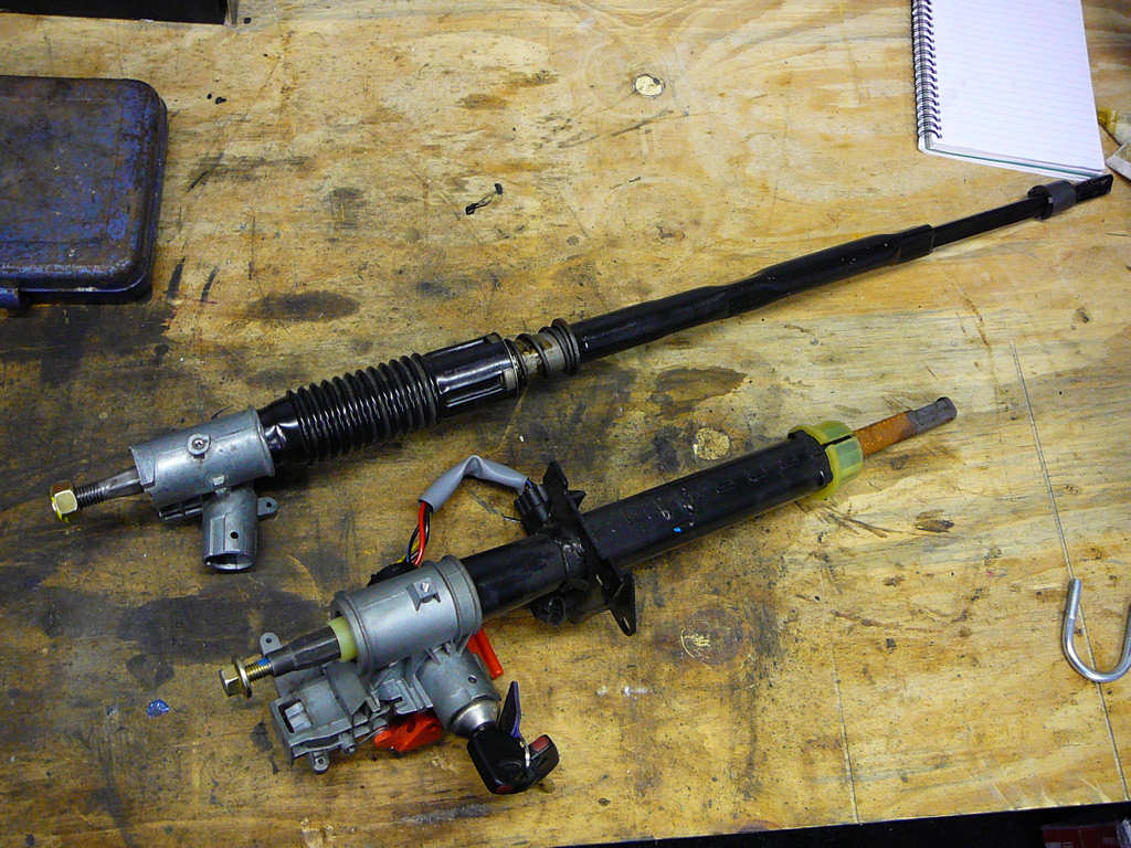
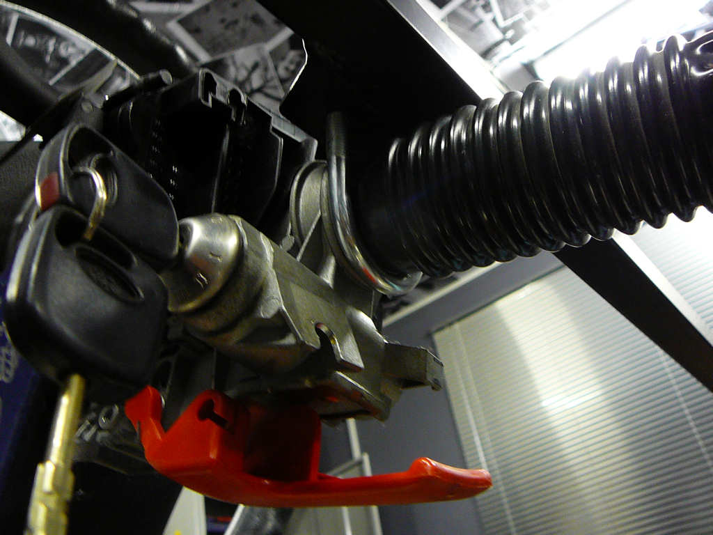
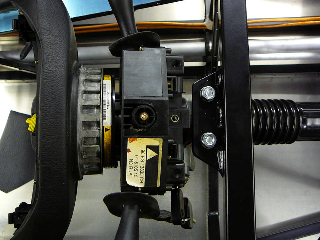
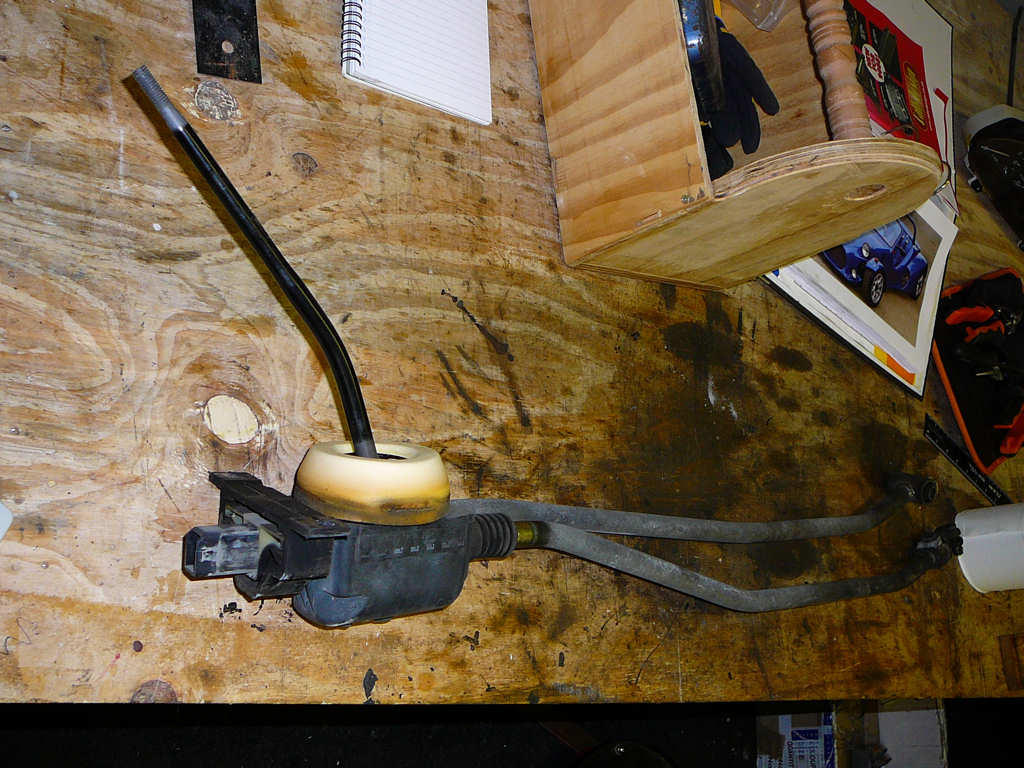
The Sierra is at the top of the image and the Fiesta is below it. As you can see, there's a bit of a difference! However, the only bit I really want from the Fiesta column is the aluminium casting, and see if it can be transferred onto the Sierra bearing tube (black convoluted bit).
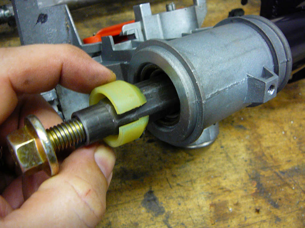
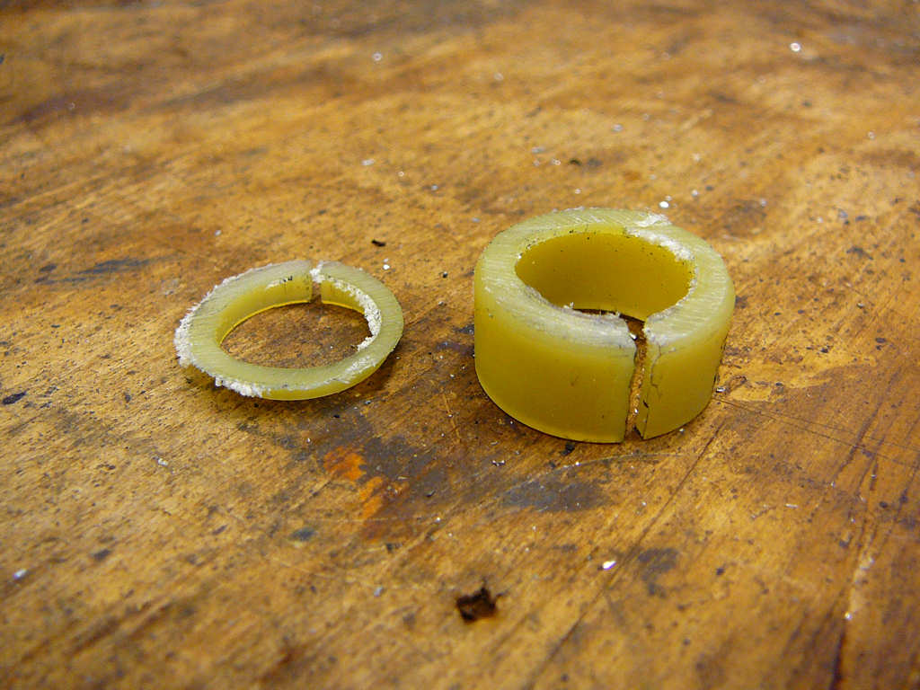
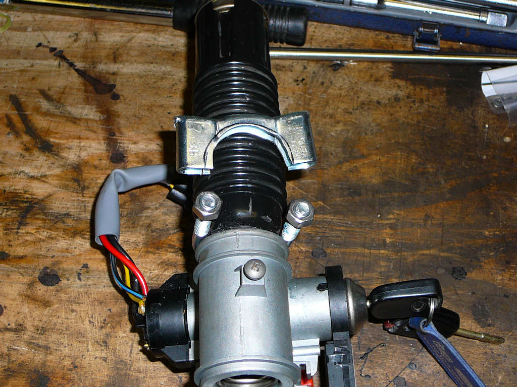
The first job is to remove the streering shaft from the Fiesta column. This is held in by this plastic bush which was simply prised out using a screwdriver.
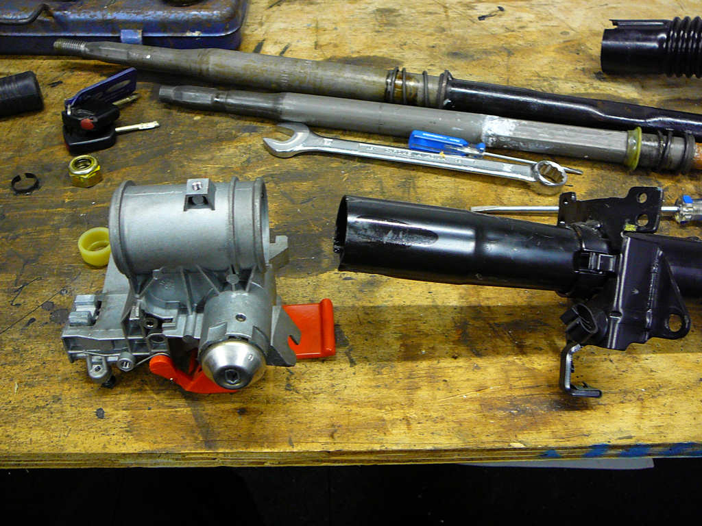
Inspection of the Fiesta parts failed to reveal any obvious fixings so I guessed that it was either glued or heat-shrunk on. After some deliberation, I gently clamped the aluminium part in my vice being careful not to crack it, and smacked the black part with a hammer. It just fell off! Phew - thought that was going to be difficult! I wonder if the same will happen with the Sierra column since I also need to separate the sluminium casting from the black tube.
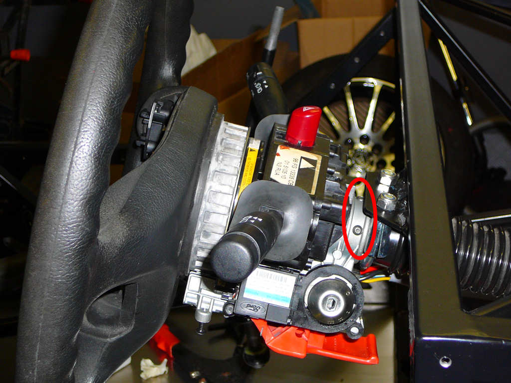
Yep - one hit and that fell apart too! This is going too well I though to myself... The Fiesta aluminium casting is a larger diameter than the Sierra black tube, but I decided that during final assembly this will be held on with copious amounts of Tiger Seal PU adhesive. For now, I dry fitted these parts together to see where any problems arose. The only issue is how to get the spacings correct so that the steering lock and the horn sliding ring assembly still work without any clashes. I needed a spacer to go onto the end of the steering shaft behind the wheel and ended up using the plastic clip removed earlier.
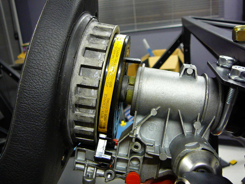
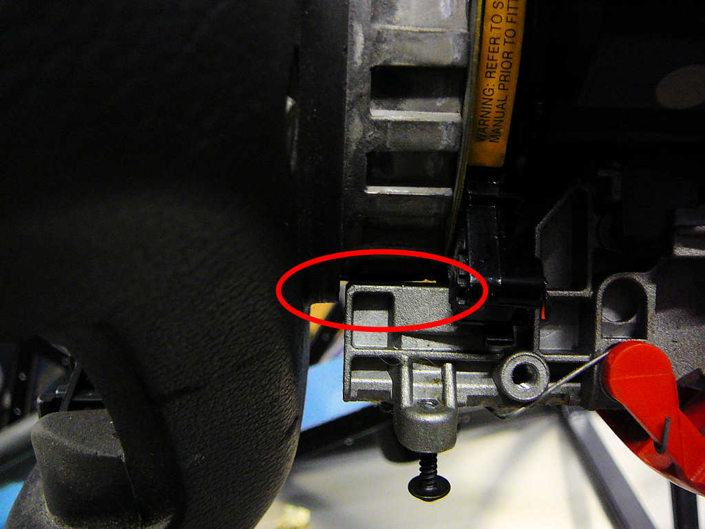
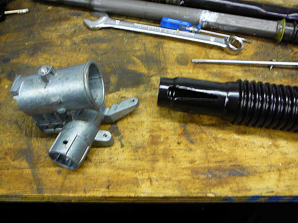
The bush was trimmed to fit and assembled onto the shaft. The main area of concern is highlighted in the image above and shows where a gap must be maintained to stop the steering wheel rubbing. The steering lock still works ok, and the sliding ring assembly seems to make good contact all the way round so it can still be used for the horn switches. The switchgear was checked to made sure it still fitted and then I disassembled it all and applied the PU adhesive, then reassembled and left it to dry.
I'm really pleased with the way this has turned out, and suprised that it was much easier than I feared.
Final job for the night was to paint the brake mounts as mentioned above, then back to the house for a mug of coffee while I update the website...
![]()
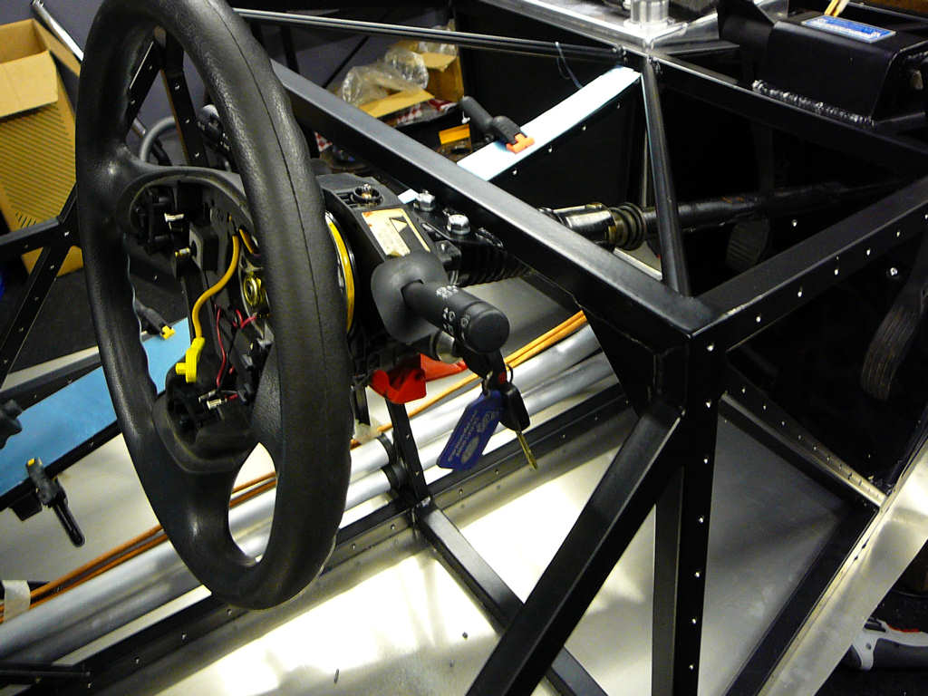
Finished off the steering column mods above by securing the aluminium casting to the steel tube to prevent any unwanted rotation. To do this, I chose a point that wouldn't interfere with the switches and tapped 3 M4 holes. M4 x 6 button head screws then locked the two parts together. The adhesive still does most of the work, but the screws help to hold the joint stable.
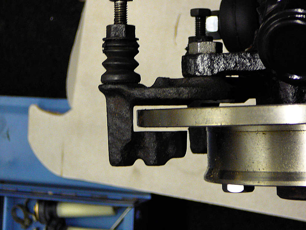
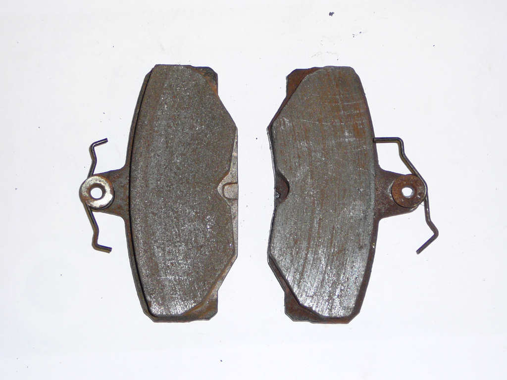
I also started fitting the rear brakes last night and I've run into a small problem:
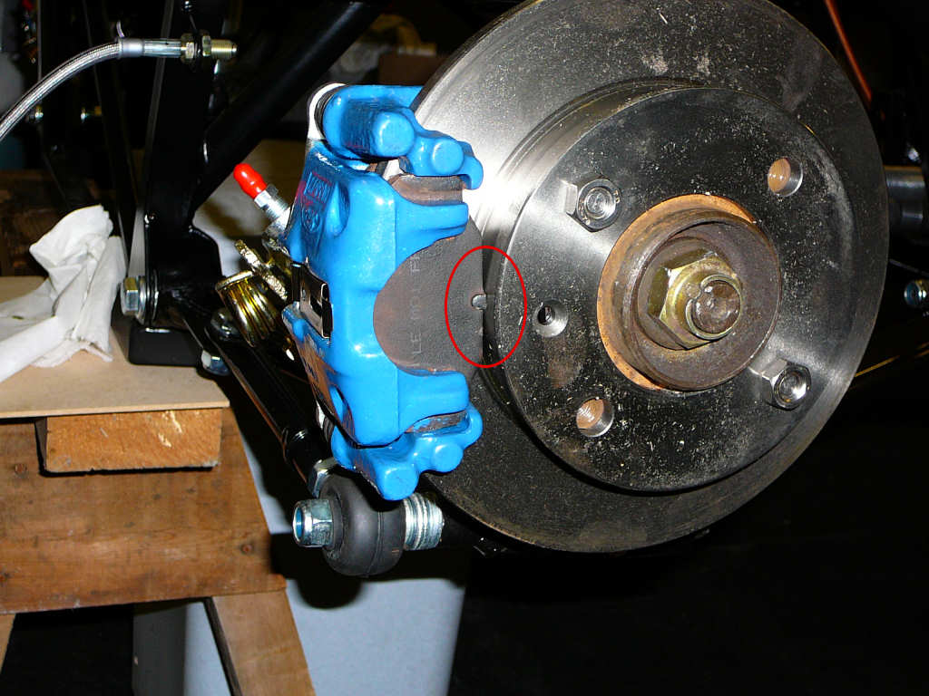
I'm using an old set of Sierra brake pads at the moment because the disks are still covered in their protective oil. As you can see on the photo above, there is a clash between the edge of the pad and the centre of the hub. I guess Mr Ford never intended Sierra rear brakes to fit correctly onto 1100cc MK2 Fiesta disks mounted onto XR2 hubs? Tsk.... Anyway - before starting any work on them I checked and re-checked theassembly to make sure I hadn't put anything on upside down or inside out, which I hadn't. I asked Alistair at Stingray if he had seen this problem before and the reply is along the lines of "Yes. Trim the pads with an angle grinder to leave a 2-3mm gap for clearance."' and of course, this isn't mentioned in the manual anywhere. I do like the way the build manual starts out with quite specific instructions "use M12x50mm bolt angled upwards to hold part a to the lower edge of part b" etc, and ends up with rather more sparce descriptions like "Fit the wiring loom"! Nevermind - it's an easy mod to do at some point over the weekend.
Ali also informs me that the parts I returned earlier in the week should be sent back to me sometime in the next few days, and that my 300lb rear springs have arrived. Woohoo!
![]()
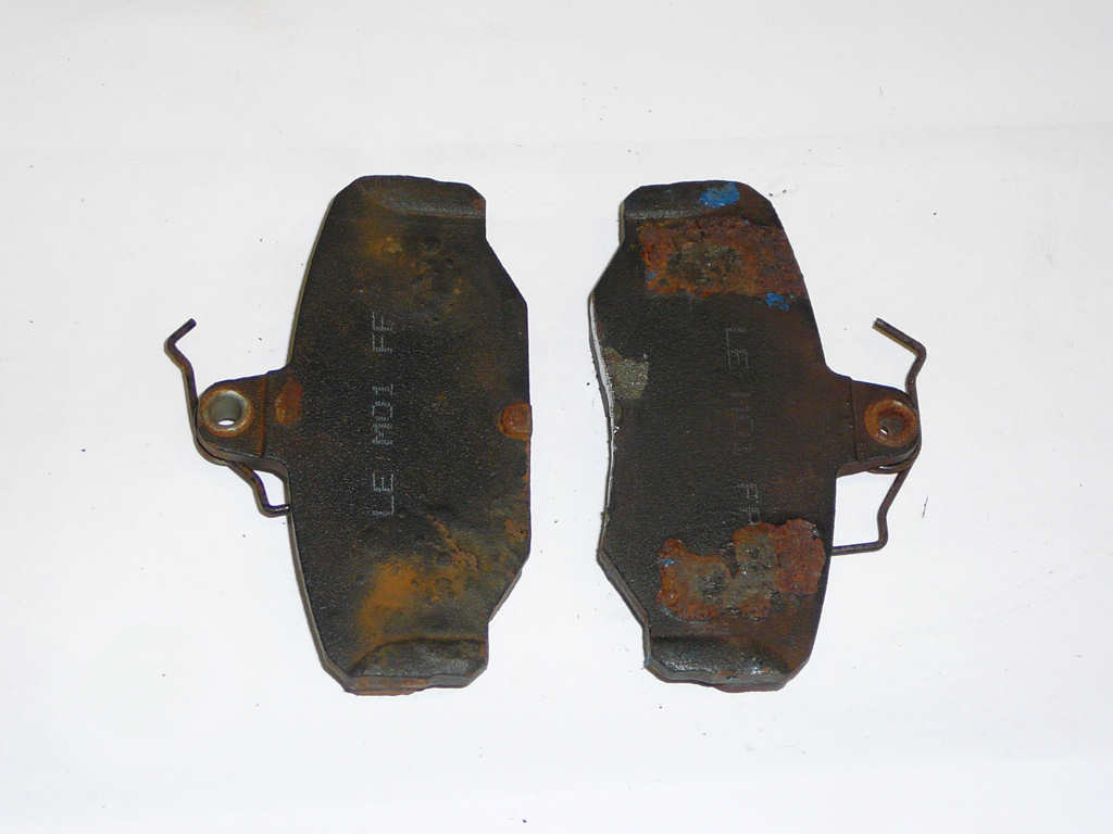
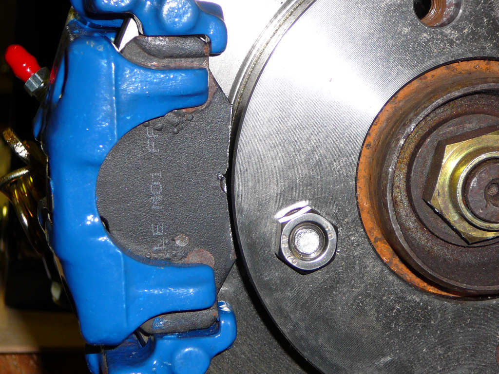
Five minutes with an angle grinder sorted out the brake pad modifications - now the pads fit correctly.
I've also fitted the clutch master cylinder. After removing the parts from the Fiesta, it became clear that the master cylinder I have is different to that in the build manual because it is designed to fit on the other side.
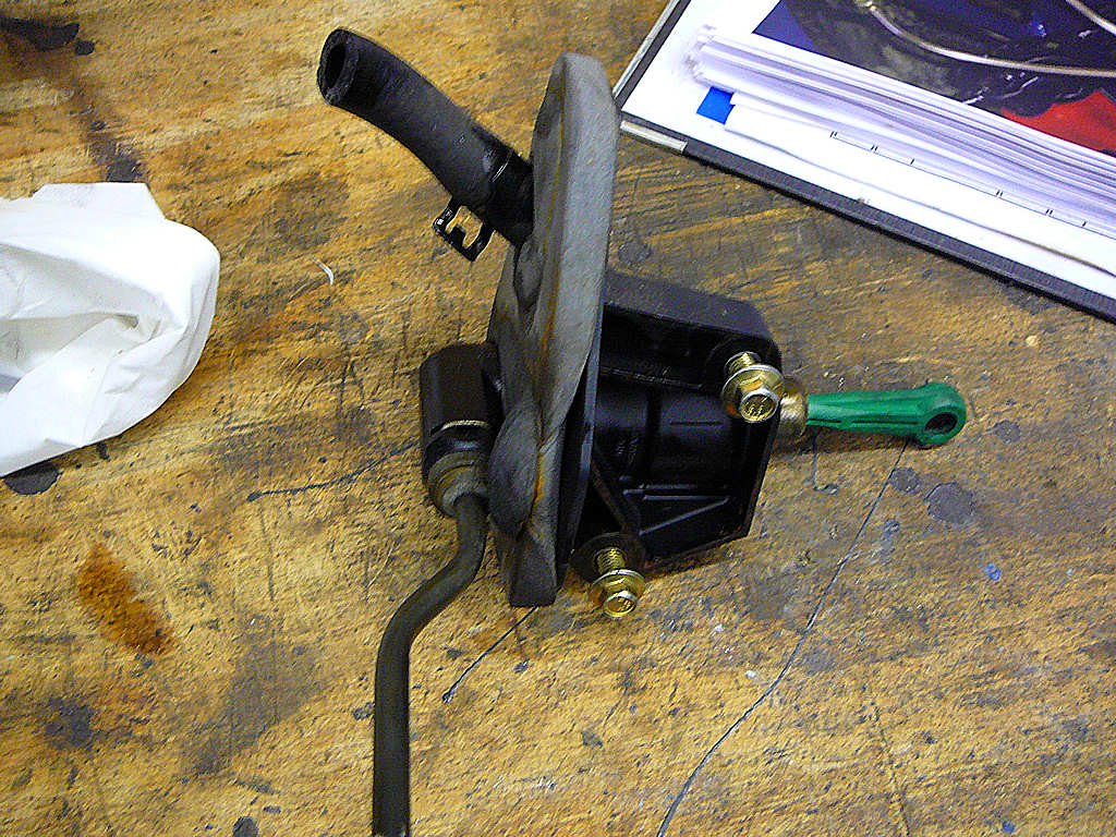
Some sort of bracket will obviously be required... So I went back out to the Fiesta to see how it was mounted originally. It transpires that the clutch pedal was fitted onto a separate bracket which conveniently sorted out the alignment between the clutch pedal and the master cylinder, and also had a sprng return and an adjustable pedal stop. I removed this bracket and returned to the relative warmth of the workshop.
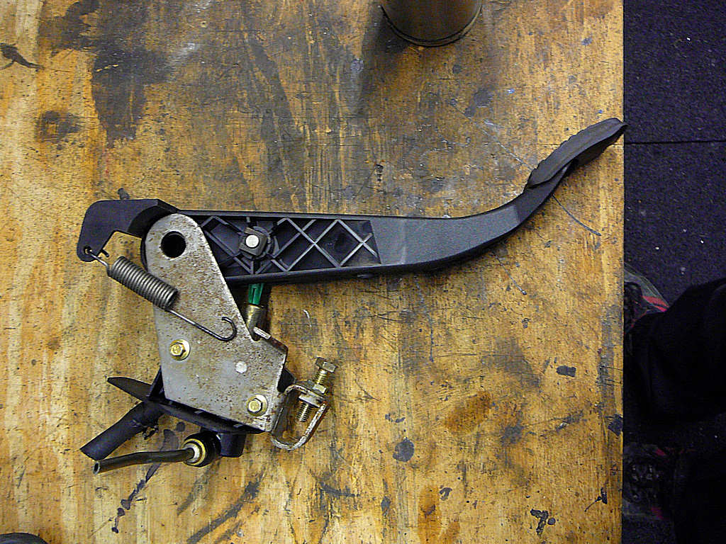
This is how the padel and bracket assembly looks once reassembled. The next step is to work out how this can be fitted onto the pedal box of the Mojo. After trying out several options, the simplest and best is just to drill two holes into the side panel of the pedal box, and bolt the bracket into place using the original Fiesta screws. I needed a couple of washers just to make sure the bracket was in exactly the right position but the end result has turned out well.
Whilst 'shopping' at the Fiesta, I also removed the gearshift which was modified and fitted to the chassis in about an hour.
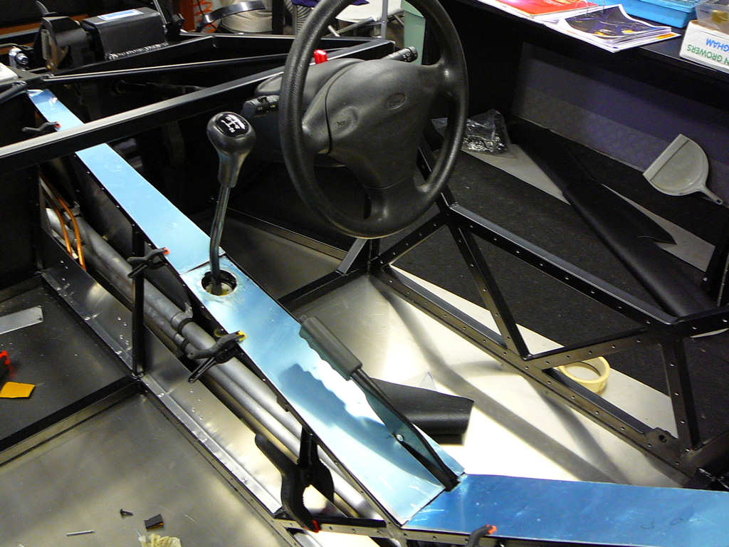
The gear lever will need to be trimmed down to a more suitable length at some point, but having the parts in place allowed me to finish shaping the tunnel top panels. These are now ready to be covered in vinyl and rivetted/bolted into place.
I did a bit of fnishing work on the steering column. In order to get the correct bolt spacing, I had to buy a 36mm clamp and the backing half of this clamp has been modified to fit the diameter of the mounting face as required. I've also modified and fitted the cowling from the Fiesta, and fitted the steering wheel centre piece after carefully removing the airbag. Note - it says 'do not disassemble' in large red letters on the back of the airbag which I ignored. If you're careful whilst taking this apart you should be ok but just because I did it, doesn't mean you should!
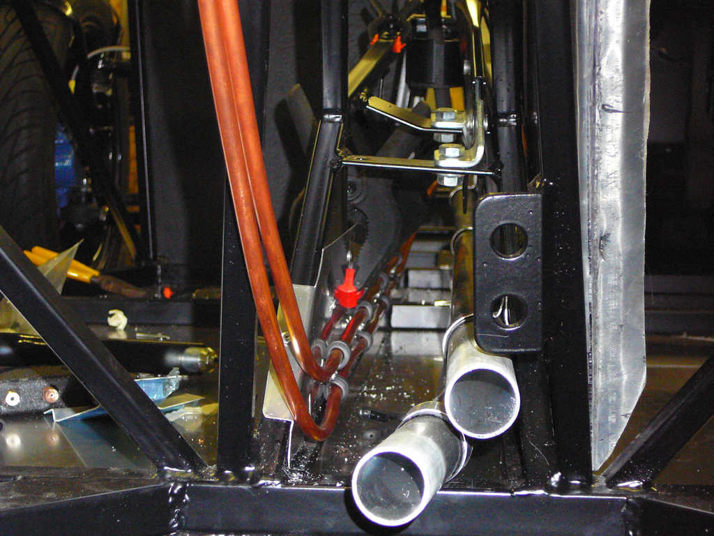
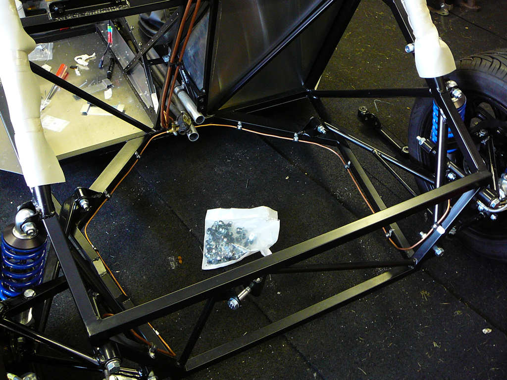
I've also spent some time pondering how to run the various pipes down the tunnel neatly and safely. I've seen several build diaries where the lines have been rivetted onto the tunnel side panels, but I would like to avoid this if at all possible. Therefore, I've shaped an aluminium panel to run along the inside of the tunnel which is used to fit the pipes onto. This means that I can put the p-clips at regular 9" intervals, and run all 4 pipes (fuel x 2, clutch and brakes) with as straight a run as possible,
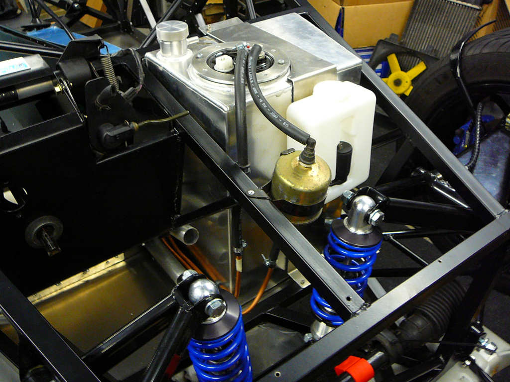
The final job this weekend is to manufacture a clamping strap for the fuel tank. A 3.5" wide strip of aluminium was cut and shaped to fit, and lined with 2mm thick foam rubber. The strap is held in place bu M4 bolts into rivnuts to allow easy extraction in the future. The washer bottle bracket is also fitted to the strap with a couple of rivets.
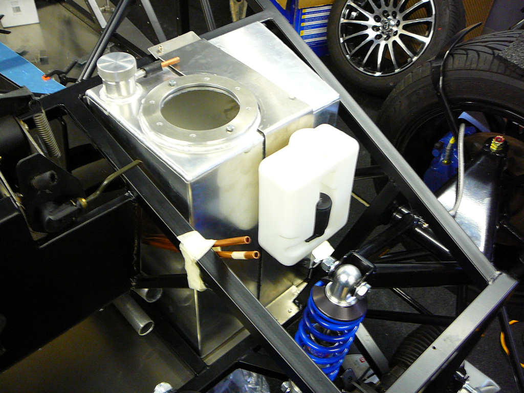
The end result is a very solid tank which shouldn't rattle or move around. I may investigate some sort of baffle to fit into the tank as it is currently just an open box....
Finally - I got some rather nice wheels from eBay (where else!). They're Wolfrace 15" alloys fitted with 195 x 50 tyres which means they're somewhat larger than what is supposed to be fitted. Therefore, the front cycle wing stays will need to be bent around to make sure there's enough clearance which I'll do once I've got bodywork. For now - here's how they look.
![]()
Well - it's almost exactly 1 month since the kit arrived and it's amazing how much you can get done in such a short time! However, I'm rapidly running out of new parts to fit to the chassis so I've spent the last few days sorting out the donor Fiesta amongst other things.
One of the parts that did arrive was the modified brake pedal from Jeremy Phillips which was duly checked for fit, painted, then finally fitted. I'm hoping to get the other brake components from Stingray this week sometime so I'll be able to connect and bleed the brake system. JP also sent the extra 4 metalastic bushes that were missing from the kit so a quick jaunt down to the local garage on Saturday morning got these fitted (their 15 ton hydraulic press make this a 2 minute job!). The only other new parts were a set of extended 50mm M12 x 1.5 wheel bolts to replace the 30mm ones on the Capri hubs since these were not long enough to take the Wolfrace alloys.
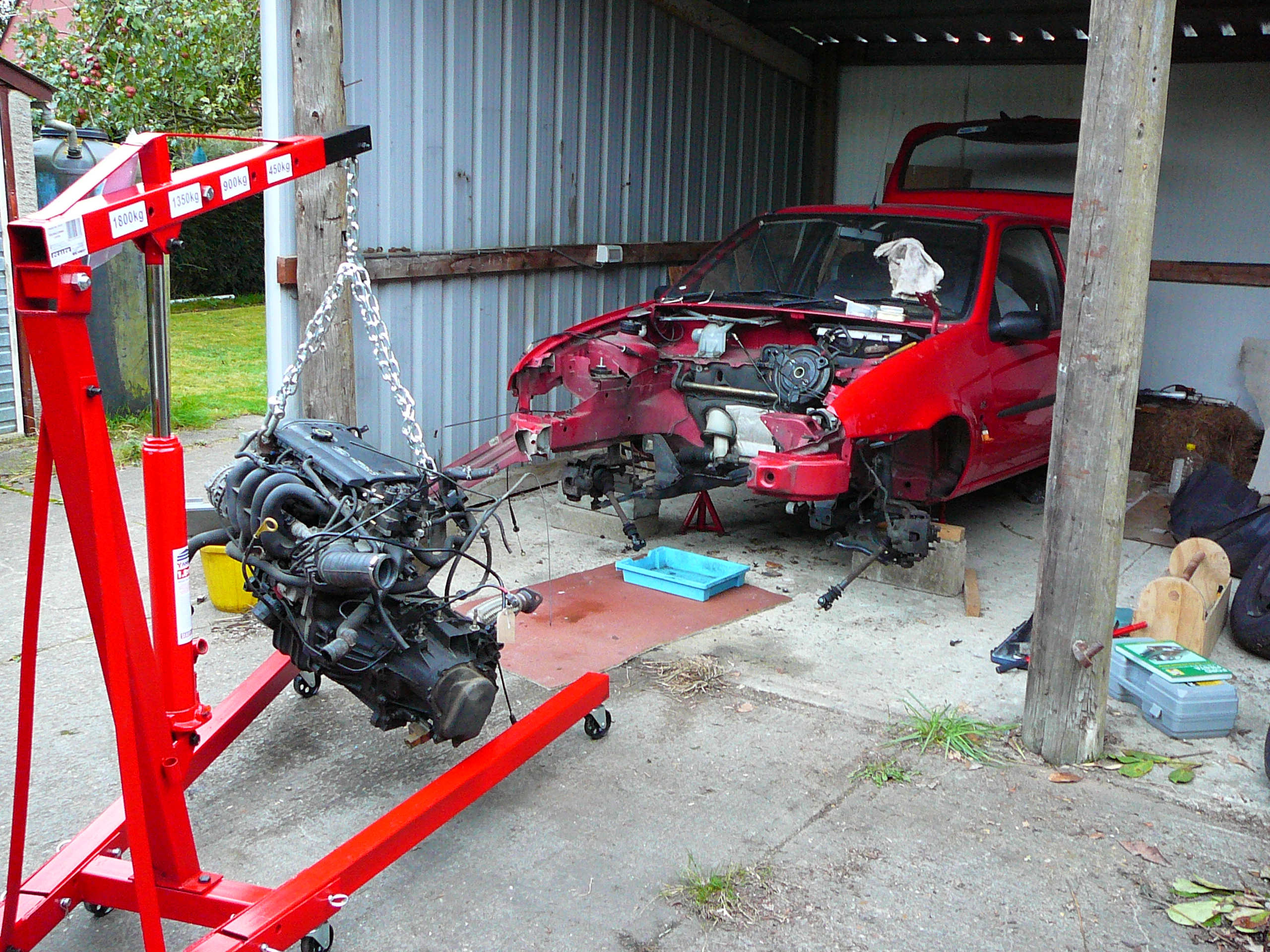
So - on to the removal of the Fiesta engine. I must admit that I was dreading this part a little since the Haynes manual made it look like an epic adventure, and the closest thing I'd done to this before was rebuilding a ride on mower. In fact, the only oil change I'd ever done before was on the ride on mower, (and the odd deep fat fryer or two.. ) and the only brakes I'd ever changed before were on my pushbike when I was aboult 9 years old. However, I've been told it's actually quite simple and I'm not in a hurry so (to quote Top Gear) "How hard can it be?"
The first thing to do is to utterly ignore the Haynes manual. This is something you come to realise shortly after owning one and finding countless errors in wiring diagrams, and whole sections that are utterly wrong! I'm just glad I didn't pay full price for my copy. But I digress.... as usual... So these are the steps I took to remove the engine:
- Jacked up the car and put it on axle stands
- Removed the front wheels
- Disconnected about a zillion wires from various parts of the engine and surround areas then removed the wiring loom. Not just disconnected it, but competely removed it. It'll be transplanted into the Mojo after some modification but it's got all of the Ford connectors and the ECU in a working condition. It's currently safely in the workshop, but more about that in a minute...
- Drain the coolant. This was a fun job - I just cut the bottom radiator hose with a Stanley knife and put a bucket under the severed connection.
- Drained the fuel tank. This wasn't a fun job. I cut a hole into the fuel filler pipe and shoved a syphon pump directly into the tank. Slowly, ever so slowly, I managed to get 23 litres of prime unleaded out! That'll keep the mowers running for a while! <Pause for an hour or two as my conscience reminds me that the grass needs cutting.>
- Drained the brake fluid.
- Clambered underneath and disconnected the flexible link that joins the catalytic converter to the rear exhaust. Noted with some joy that the catalytic converter is so new it's still shiny. :-)
- Removed the transmission stabiliser bar. This made the engine drop rather alarmingly so it was hastily popped back into place until later.
- Cut the CV boot gaitors. Removing the front suspension to release the CV joints sounds a bit tedious for a car that is being scrapped, so I'll just let the inner joints fall out when the engine is removed.
- Removed the radiator, and got liberally doused with some leftover coolant. Note - don't be under the car when you do this!
- Removed the headlights, and front grill.
- Removed the inner wheel arches.
I then spent some time trying to work out the best method of attack. The engine cannot come out through the bonnet since there just isn't enough space. The engine could come out from underneath, but then the legs of the engine hoist are in the way. I'd also then have to lift the entire Fiesta up ludicrously high to get the engine out. There's not enough room underneath to get a trolley, so the engine would have to be dragged which sounds like a very bad idea! Or.... I could chop out the two front chassis members and just pull the engine straight out. I thought this would require the angle grinder since these chassis members are designed to take frontal impact in the event of an accident so I was visualising them as being rather girder-like. For a giggle, I had a quick hack at one side with a junior hacksaw (yes - a junior...) and I cut through like a knife through butter! Lunging for the larger hacksaw, I completed most of the cuts in about 5 minutes. Then the hacksaw blade broke. And it's my last one. And it's 5pm on a Sunday afternoon so I can't get another one. "Nevermind" I thought - "This stuff is weaker than you thought!" so I just bent it out of the way. My advice - don't have a frontal impact in a Fiesta. There's not much up front! So - with the chassis members removed it was a relatively simple job of hooking up the hoist and taking the weight of the engine. Then follows the trepidatious removal of the engine bolts during which I remembered that I had put the transmission support bolt back in earlier! This was quickly removed. The CV joint gaitors also tried to put up a bit of a fight but a Stanley knife soon sorted them out. The CV joints themselves are not held in by any circlips etc and just pull stright out. A Chuckle-brother-esque sequence of "to you, to me, up a bit, down a bit" later and the engine was out! The engine still has all of it's oil inside it (it was only changed around 100 miles ago) and the transmission is also still full of it's oil. This will need to be drained when I remove the driveshaft stubs from the gearbox later. I've left these in for when I clean the engine to prevent any gunk being let into the gearbox.
As mentioned before, the engine wiring loom was removed and moved the the workshop. The engine loom consists of the auxilliary fusebox, all of the engine sensors, the headlight wiring, the ECU wiring, and the battery wiring. The interior loom is attached to the engine loom by 3 connectors at the back of the auxilliary fusebox. I'll remove the interior loom from the Fiesta later... Every connector was labelled as it was removed which helps enormously when there's just a bare loom in front of you on the bench!
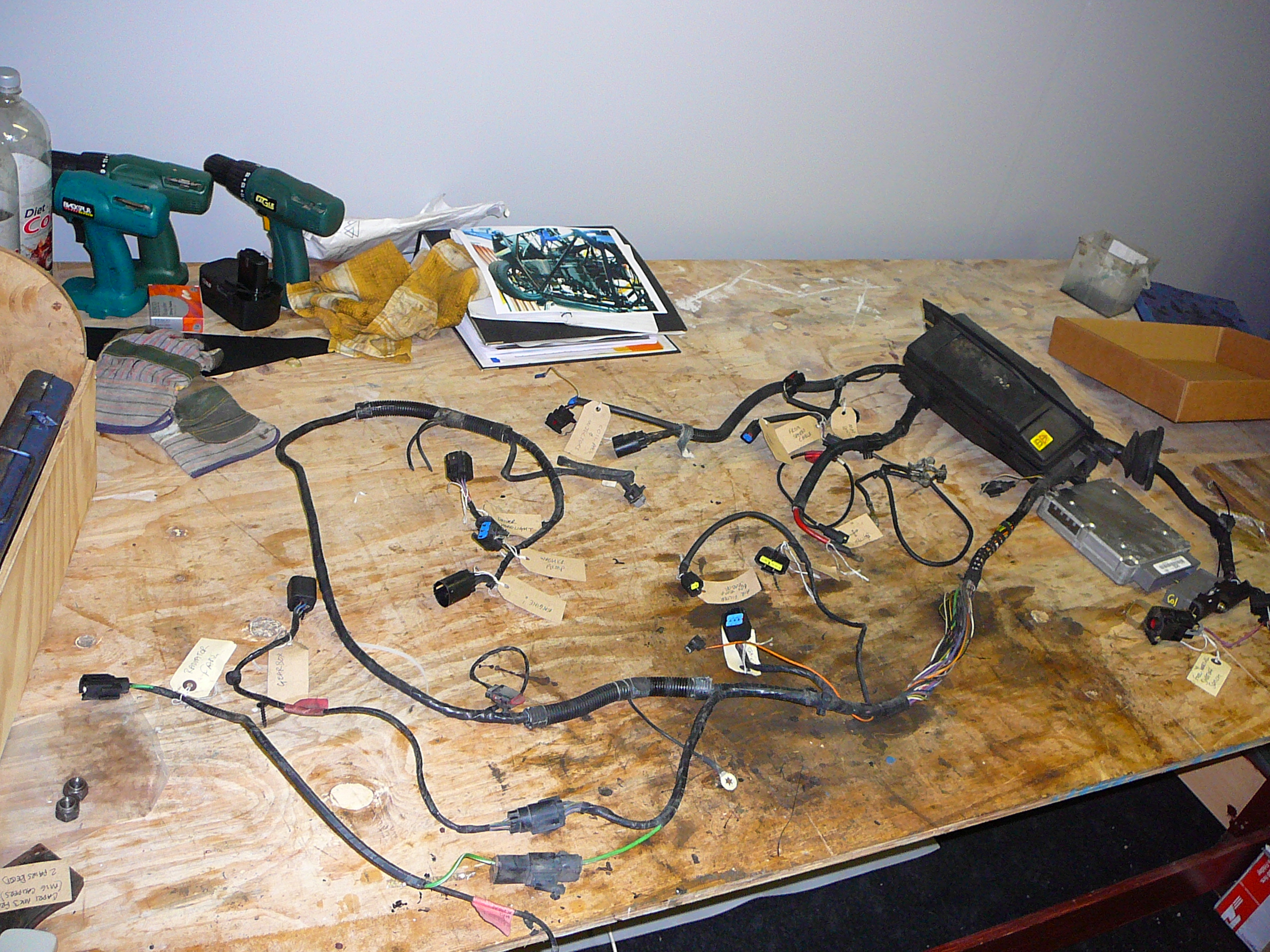
This loom will need some drastic surgery before being fitted to the Mojo. I have considered making my own from scratch which isn't that daunting as I'm an electronics engineer by trade. However, if you go to a builders house there's always some unfinished building work. If you go to a decorators house, you can guarantee that at least one room has been waiting to be painted for some considerable length of time. If you go to an electronics engineer's house, you can guarantee that their wiring loom for their kit car isn't quite finished! There's nothing wrong with the Fiesta loom and I know it works perfectly. It's got all the right connectors, albeit in the wrong places, but that's easier to fix than starting from scratch. It's also a lot cheaper! If I can save a few sheckles on wiring paraphenalia, then there'll be more to spend on fun bits later!
Anyway - it's been a succesful week, and it was topped off by a surprisingly entertaining Monza GP too! Marvellous.
![]()
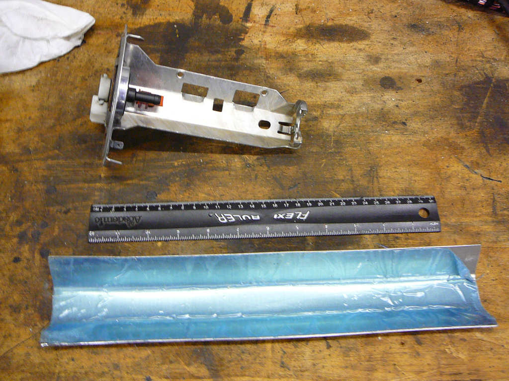
The workshop is now swamped with the heady aroma of petrol! I've removed the Fiesta petrol tank which still managed to have about a litre of unleaded in it even after I had drained it as much as I possibly could! Next, I removed the petrol pump and level sensor, along with the fuel filter.
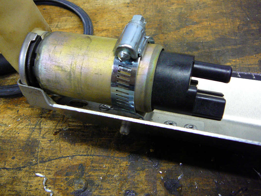
The first job was to modify the fuel pump bracket to accomodate the extra depth of the Mojo tank. This requires cutting the bracket and lengthening it with a suitably shaped length of aluminium. For reference, the overall length of this assembly is now approx 435mm from the inside of the mounting flange to the bottom of the pump. The pump is a relatively heavy item so I also made a little aluminium bracket which was rivetted onto the main bracket, and used a jubilee clip to secure the pump to it. The pipe that connects the pump to the white outlet on the top of the tank also needed lengthening and this was achieved by a couple of bits of rubber pipe and a spare length of 10mm copper fuel pipe.
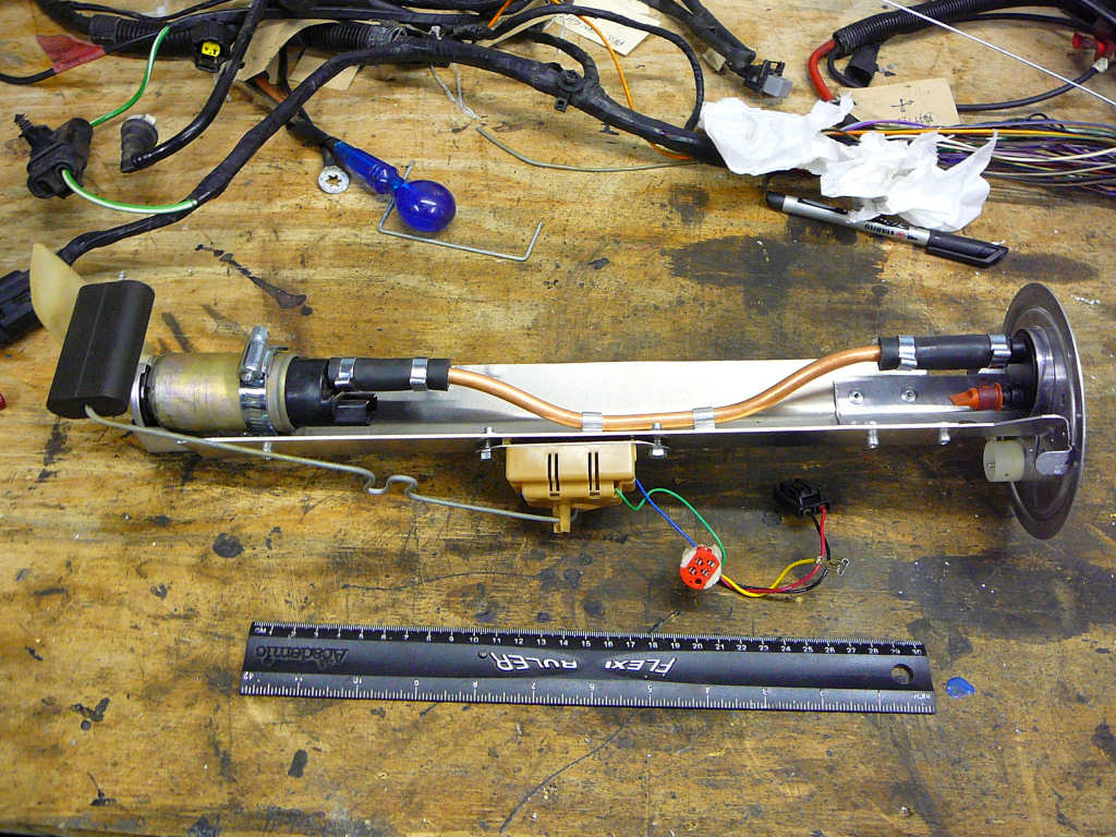
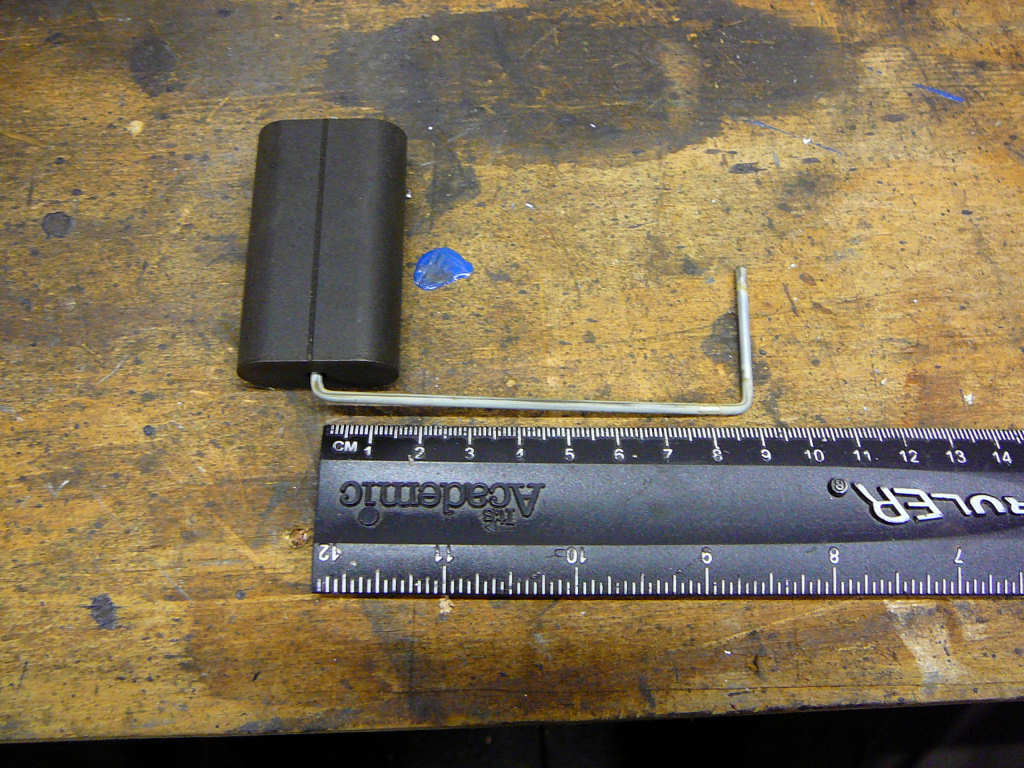
I also looked at re-using the level sensor. To do this, the swinging arm needed lengthening to allow for the height of the tank. There's not a lot of room inside the tank so finding the correct position to allow the arm to swing fully in was not simple, but it seems to be ok with an arm length of 225mm. It is of course quite possible that the fuel gauge I end up using won't be compatible with this sensor, but at least I now have the option. If it needs to be replaced with another unit later on, then so be it. For the record, the sensor reads between around 20 and 200 ohms between empty and full. Finally, the wires were extended to remake all of the connections (not shown on the photos... sorry).
Now slightly woozy from the fumes, I set about mounting the fuel filter (thanks Michael B!) and plumbing the whole lot together. The filter is mounted onto the fiesta fuel tank with a simple bracket which was cleaned up and painted black, and shaped to make it fit around a chassis tube. A couple of rivets and some TigerSeal makes sure that it won't be going anywhere! The Fiesta fuel plumbing also makes use of a number of quick-release fittings which were separated from the Ford pipes and reconnected to rubber hose. A couple more p-clips were used to finally fix the pipes into their correct places and the pipe clamps were tightened. I'll replace the filter later, but it'll be fine for testing at the moment. Another job done! Now what's next....
![]()
A box of parts has arrived from Stingray! This includes the lower steering link, the 300lb rear springs, the steering rack clamps and the brake lines. These are currently in various states of being fitted and I'll take some photos over the next few days.
The engine has been degreased and moved into the workshop ready to be worked on. This involved the use of copious amounts of Gunk, a stiff brush and a hosepipe. It's important to set the hose to high flow with low pressure to make sure that no damage is done to the engine. Jet washing is not a good idea! I also discovered that Cillit Bang is particularly effective as a degreaser for engines and is significantly cheaper than Gunk!
The first job is to check the belts, and it looks like the timing belt is almost brand new! The auxiliary belt however is looking a little bedraggled so it will be replaced.
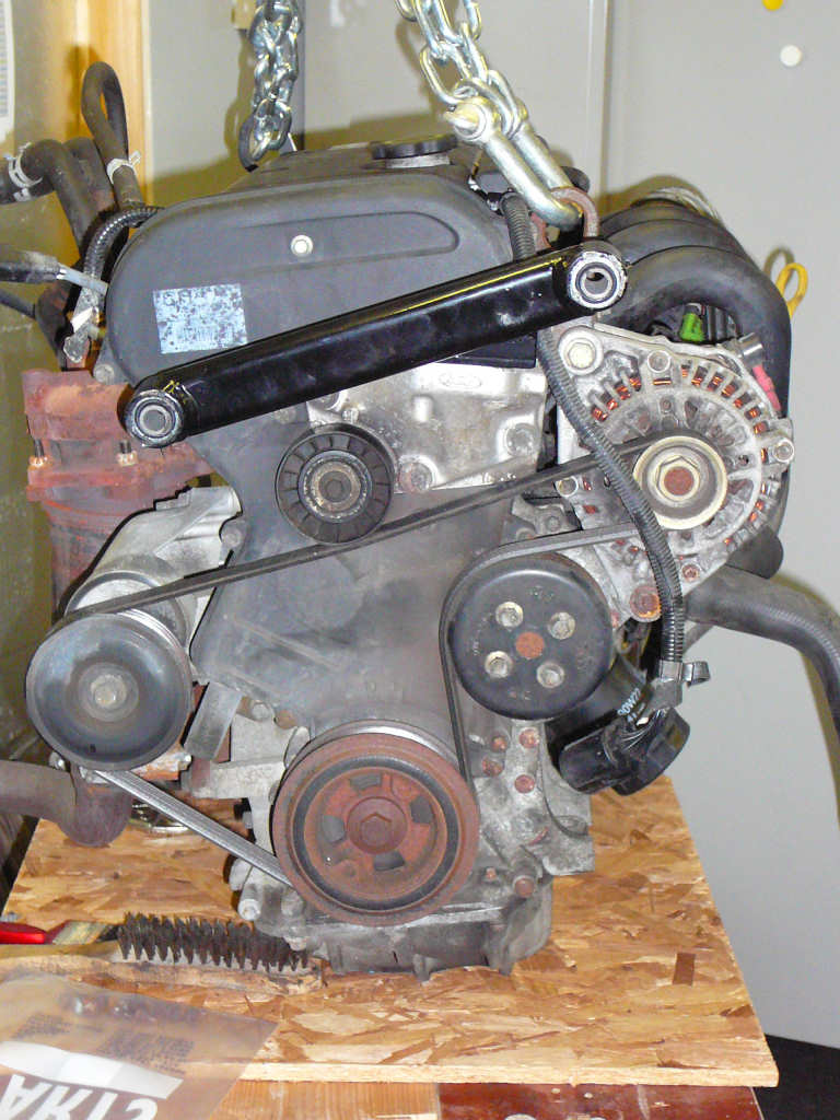
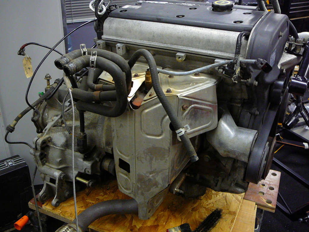
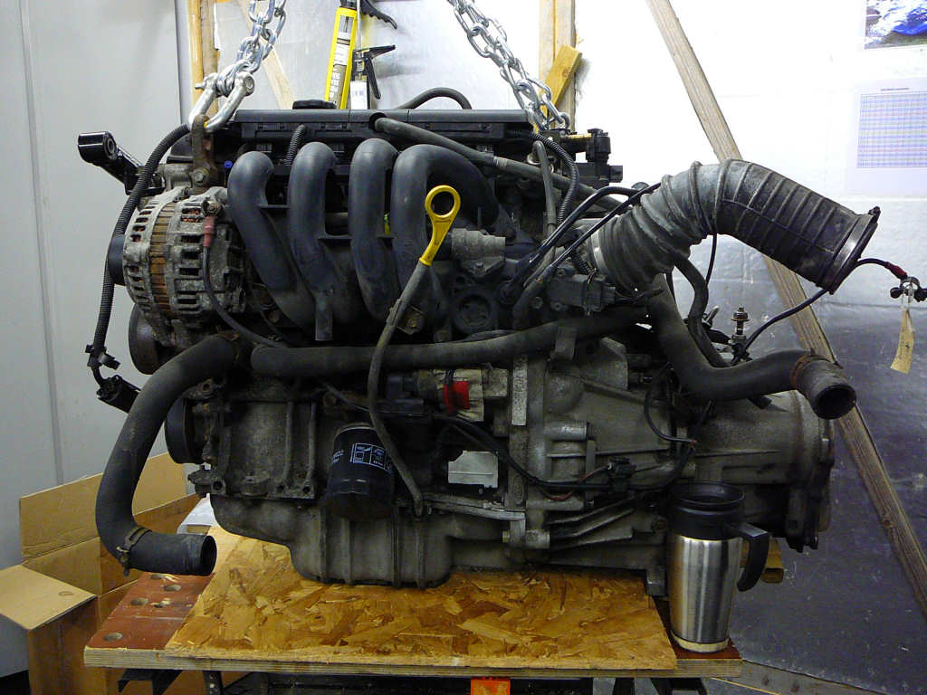
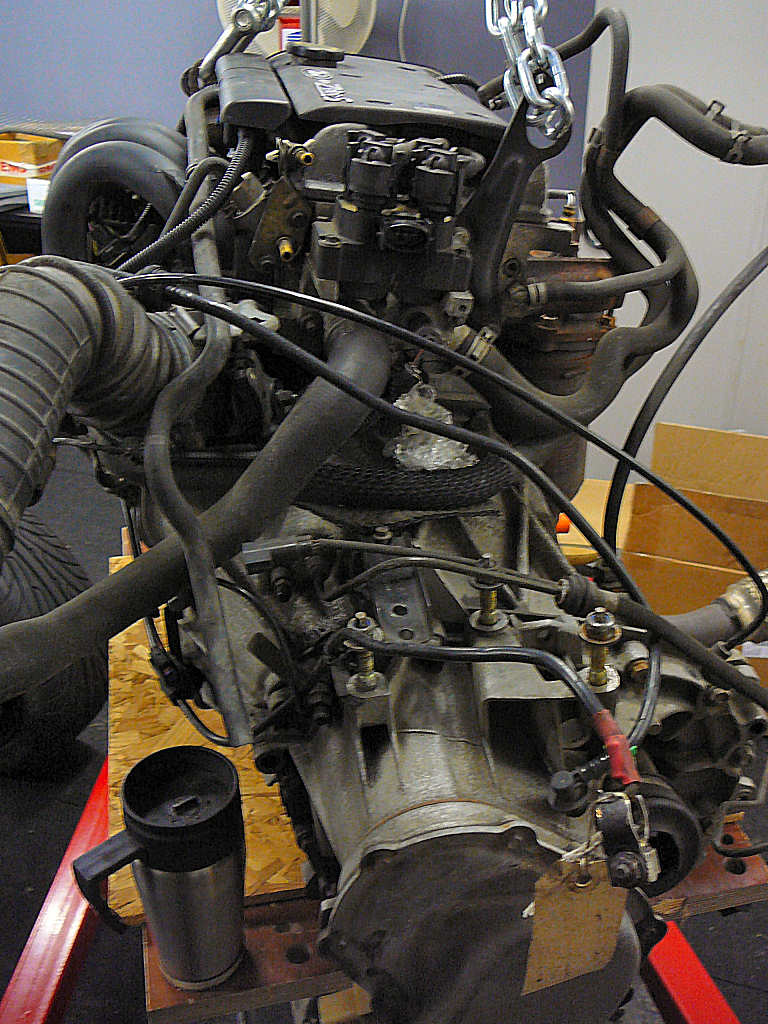
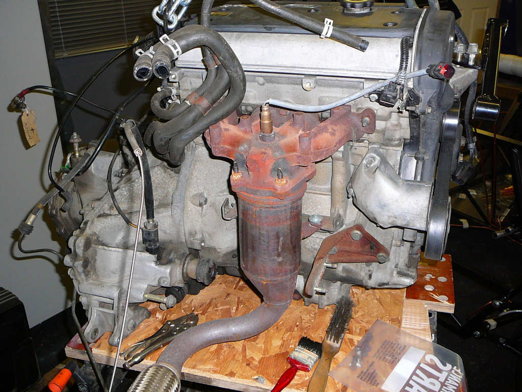
I've removed the exhaust manifold and catalyic converter as these will need significant modification so that it will fit into the confines of the Mojo engine bay. I may still replace these with the complete Sylva system, but it's definitely worth trying to reuse the Fiesta parts to save cost.
The next process will be to clean the engine using wire brushes etc to remove the oxidised aluminium. While not essential, it's going to be nicer working on a clean engine and it reduces the risk of muck getting into any exposed ports.
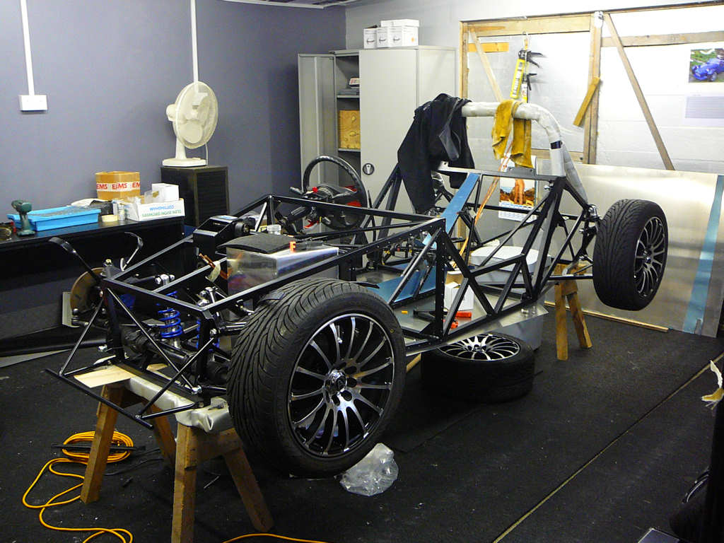
In order to make enough space to get the engine into the workshop, the Mojo had to be lowered onto it's wheels. It's still light enough (just) for two people to lift each end in turn, and one other brave person (wife) to reach under and remove the build stands. I know other people say this all the time, and I know I've seen Mojos up close so should be used to it, but nothing - absolutely nothing - can prepare you for how low the car looks when it's down on the ground!
It also becomes immediately apparent how stiffly sprung the Mojo is. I'm running 200lb front springs, and 300lb rears, but this makes the suspension on your standard production car look like a huge bucket of trifle! Note to self: Mind the potholes.
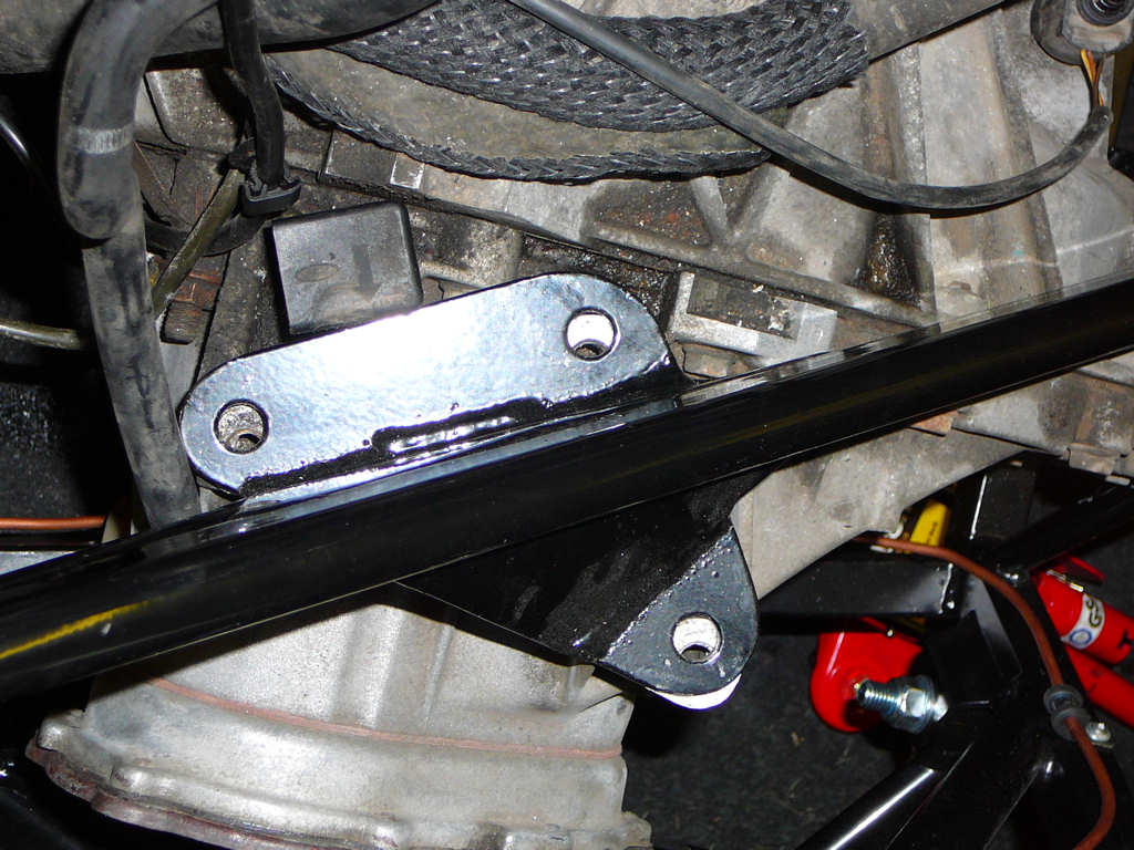
I've been advised to check the mounting brackets fit onto the engine now before even trying to fit the engine into the Mojo and there is a small problem with the gearbox end mount. Firstly, the powder coat needs to be removed from the 3 top holes as these are a little tight. Secondly, there is a small arm on the main engine mount that locates down low onto the gearbox which helps to stabilise the engine. It doesn't line up. In fact, it's about 1/2" out as shown below.
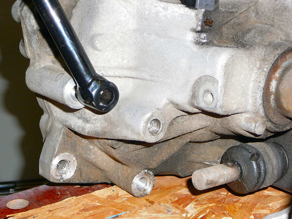
Other builders have apparently cut and re-welded this piece to overcome this problem but I don't have a welder, so I've 'physically adjusted' it to fit <ahem>. This involved putting the arm section into a vice and applying a considerable amount of pressure. Slowly, step by step, the arm position was moved and now it fits ok. It's a tribute to the quality of the Sylva chassis that the weld didn't crack!
I'm hoping to get all of the engine jobs done over the next week or so, and then we'll see if the engine fits into the chassis!
in the meantime, I'm also testing how various items survive in petrol. This is because the wiring and pipe mods to the extended fuel pump mentioned previously are of a temporary nature for testing, and will be replaced eventually. I've got some jars of petrol sitting on the shelf with a number of bits of pipe, heatshrink, cable, p-clips, cable ties etc immersed in them. These have been sitting for a couple of days now and so far everyting seems to be ok. The fuel pipe is marked as BSAU103/2 but I don't think it's supposed to be fully immersed in fuel. We'll see....
![]()
Payday has heralded the arrival of some new parts to fit ontot the Mojo! Nothing really that major, but I've received some 5mm wheel spacers to help with wing stay clearance issues with the front tyres, some M14 steering rack locknuts, a high level brake light, some more rubber lined p-clips, some petrol pipe clips and some 40mm jubilee clips. Incidentally, I got the rubber lined p-clips from RS components. The typical price for these seems to be around £3-4 for 10 online, but I got a bag of 50 for about £18. Bargain.
So, with these parts in hand, the first job is to finish the rear brake lines. I got Stingray to remake these since one of them was a bit short previously, and Ali has done me proud - they fit perfectly now. A bit of bending and clipping and it's job done.
Now that these are done, I can seriously start thinking about fitting the engine. The last preparation job I need to do is to remove the remnants of the old drive shafts because I have a sneaking suspicion that this will be much easier on the bench than when the engine is in the Mojo! Firstly, the gearbox oil was drained which is a foul smelling nasty messy job! Nothing can prepare you for that first lungfull of gear oil vapour... A crowbar soon levered out the short side CV joint, and then a drift was used to hammer out the longer side from inside the differential. I haven't got any photos of this bit since I've already broken one digital camera in the workshop (don't ask...) and I didn't want to ruin my good one by getting my oily hands all over it! The old oil has been stored in some 2 litres Coke bottles until I can get up to the dump with it where they've got the proper oil disposal facilities.
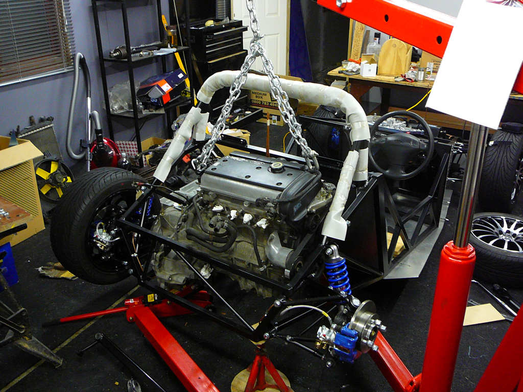
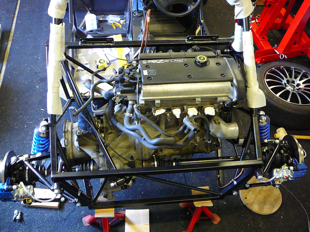
The tape measure tells me that the engine is going to be a tight fit. Really tight. It wasn't wrong! However, at the rather odd time of 10pm, I started to lower the engine into place. From experience, I know that I'm a bit more alert later in the day - in fact I don't function properly until around 10am most days and seem to peak around midnight but I guess that's just the way I am. Since I was on my own for this process I used a step-by-step process of lowering the engine a few mm, checking clearances, chocking gaps with pieces of wood where necessary until the engine was fully lowered into place. It's amazing how the english language lets you use so few words for such a fiddly, awkward and drawn-out procedure! In all it took an hour or so of steady progress to get to this point:
And that was the easy part! Now came fitting the engine mounts. I was prepared for this to be a bit of a struggle, which is exactly what it turned out to be. First step is to remove the engine mounting studs from the gearbox and block or there will be absolutely no chance of fitting the mounts. With this done, the trolley jack was called into service to help support the gearbox end. I first fitted the driver-side engine mount which required a bit of jiggling around, and some leverage from the trusty broom handle and a rubber mallet. Eventually though, it was in place and the bolts were loose fitted to stop it falling out. It seems to always be the way that you are forced to use a mallet to get a bolt into a hole, then as soon as you turn your back it manages to succumb to the rather feeble force of gravity and fall straight out onto the floor! How do they do that?! Anyway - on to the gearbox side. Apart from the problem from the other day of the lower arm not fitting, it also transpires that the 3 main bolt holes don't line up either.
This required a bit of filing, some 'physical modification' of various mounts and plenty of leverage, but after about half an hour, one cup of industrial strength coffee, a couple of skinned knuckles and a fair amount of offerings to the gods of foul language, the studs were re-fitted and the fixings hand tightened. The time was now 1:30am, and my energy levels had gone way past prime, so that'll do for tonight. Time for a rest.
![]()
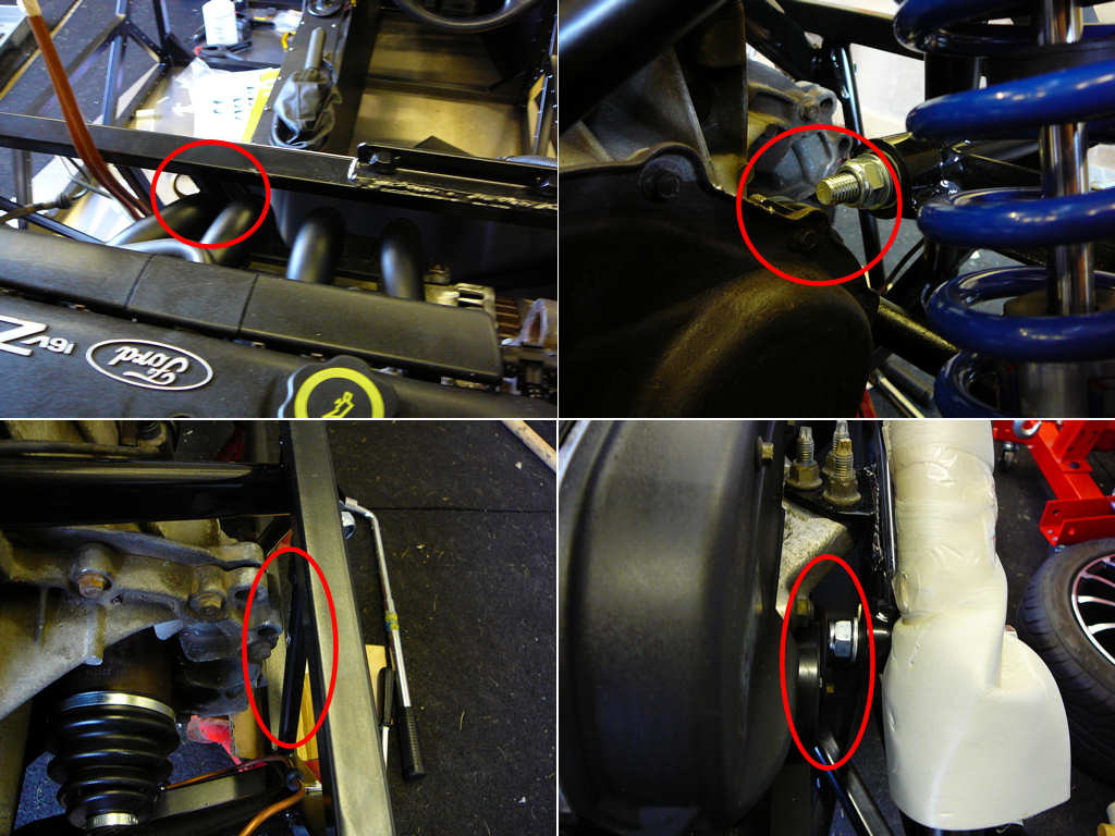
The previous nights efforts were checked today, and the engine mounting bolts were torqued up tight. You know how I said it was tight... here are some photos of the various corners of the engine and the bits of chassis that they nearly touch! Getting the dispstick out could be interesting.
Now that the engine is fitted, I should be able to crack on and get the clutch hydraulics fitted, the fuel lines can be finished and the coolant pipes can be plumbed in. I can also make a start on getting the engine wiring loom modified now that I know where everything is in relation to each other. I've planned these jobs along with many others to be done during October, and I'm leaving jobs ike the exhaust until November-ish. I'm also going to be ordering the bodywork and some other bits this week so I should get these for the end of October.
For now though, the task I've given myself today is simply to fit the driveshafts. This turned out to be a nice easy job compared to the efforts of last night, so I took my time over it. The old CV boots were binned, the CV joint grease was changed (another mucky job, but strangely satisfying), and the new boots were fitted. The rear uprights were loosened so that the driveshafts can be slotted into place. A bit of a shove, and the nice reassuring 'tick' of circlips popping into place meant that all was going well. The rear uprights were returned to their... er... upright... position, and the pinch bolts reinserted.
I started to fill the gearbox back up with oil, but it soon transpired that there was a leak and smelly oil was pouring out the bottom of the gearbox! It turns out that the switch on the gearbox that is used to sense reverse and neutral, had taken a bit of a knock at some point. It's in a bit of a vulnerable position and I'm not sure if it was during removal from the Fiesta, or lowering into the Mojo. Anyway, the casing is cracked causing the leak and I need to get a new one. I also noted that the switch housing fouls on the lower chassis member when the engine is in place so I shall cut some of the housing off of the new one and solder some leads directly onto it and connect it into the loom elsewhere. There's no way to get the connector into the switch as it was on the Fiesta because this chassis bar is in the way. I'll try and remember to take some photos of this when the new part is sourced which should help to make it all clearer.
Most of the rest of the day was spent tidying up a few odds and ends and watching the Singapore GP which was eventful to say the least!
![]()