


![]()
Another month goes by!
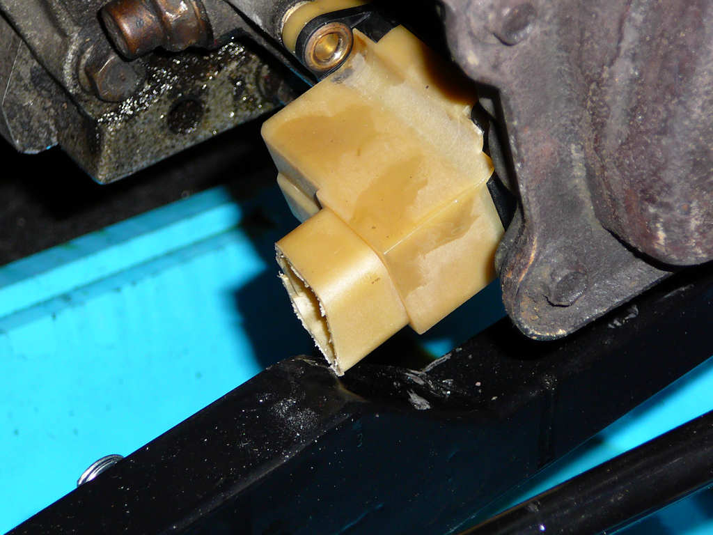
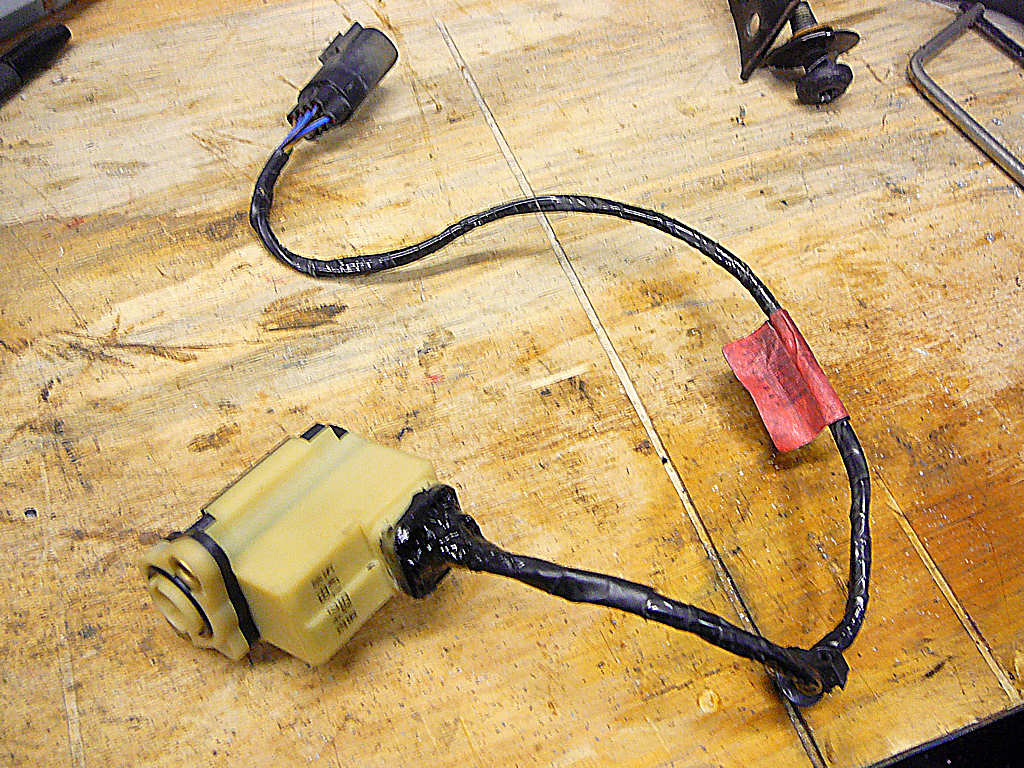
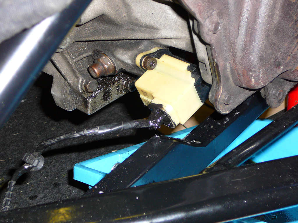
As promised, here's a photo of the gearbox switch issue. As you can see, this is the old switch that has been hacked around a bit. I've sourced a new one direct from Ford, which will also need to be modified to resolve the clearance issue. I'll cut the shroud completely off the new one and solder the wires wirectly to the contacts. Luckily, the loom connector for this switch is fitted to wires that are about 18 inches long with another connector on the other end. Therefore, I'll just cut off the connector at the switch end and I'll still be able to connect and disconnect the switch from the loom. Hope that made sense...
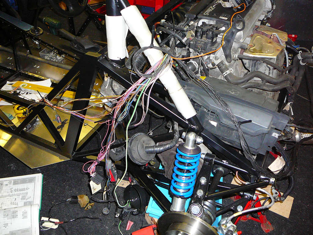
While we're on the subject of wiring, I just couldn't resist the pull of the loom-in-a-box in the corner of the workshop. So I got the engine loom out and started separating the wires.
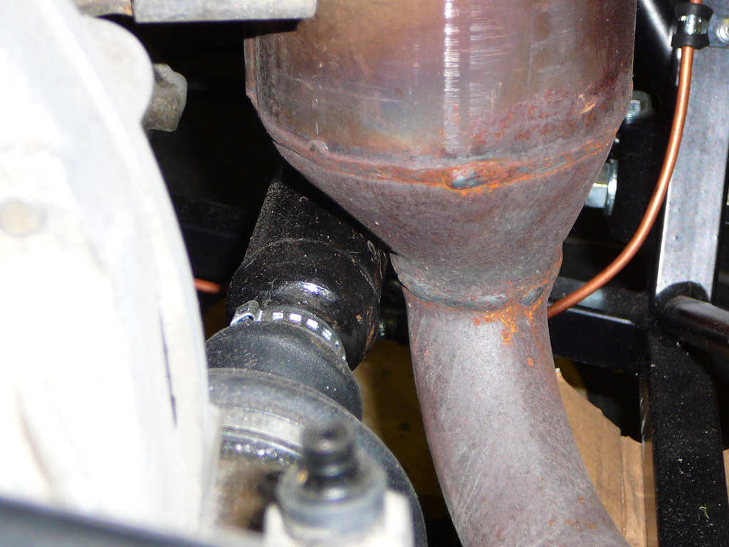
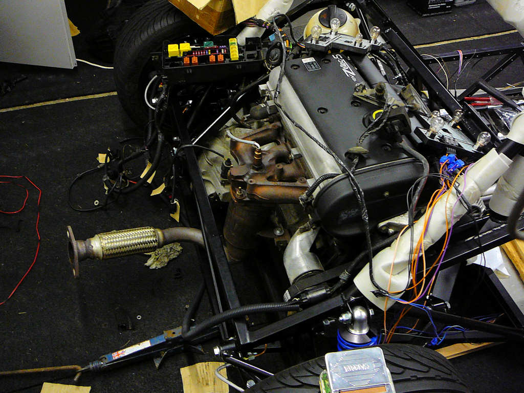
I also started mocking up the exhaust to see if the Fiesta manifold can be re-used. The short answer is 'probably'. There is a clearance issue between the bottom of the catalytic converter and the driveshaft. In the original Fiesta installation, the driveshaft was a smaller diameter and was split into 2 sections with a CV joint partway along it. This second CV joint was supported in a bearing block bolted to the engine block, but unfortunately the other end is not compatible with the XR2 hub. Therefore, I will need to move the catalytic converter somehow. Not much, maybe only 10mm or so. My current plan is to put a spacer block between the engine block and the exhaust manifold so that the cat is a bit further towards the rear of the chassis. I'll talk to Jeremy about this next week because he may be able to source a suitable spacer from one of the manifold he gets made up. More on this to follow. For now - here are some pictures!
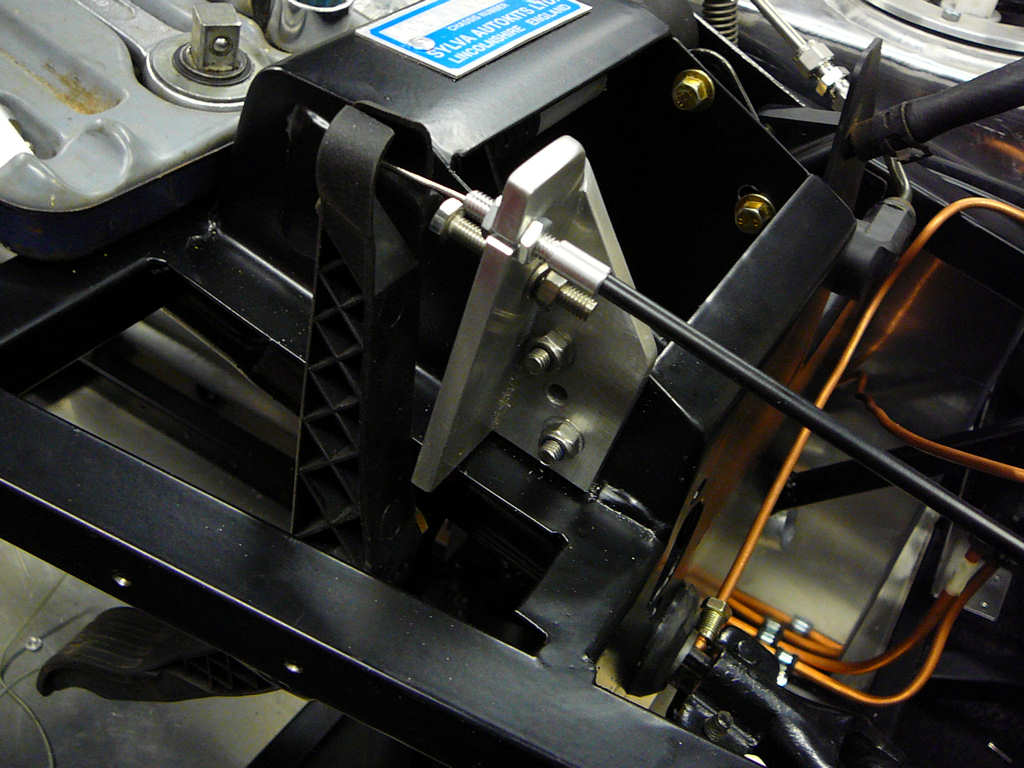
I've installed the throttle cable. I got a 3mtr universal one from RCS cables for £14 and made up an adaptor to fit the end onto the Fiesta linkage. I also made up a bracket to go behind the accelerator pedal to support the other end of the cable. This will need final adjusting when the engine gets fired up.
![]()
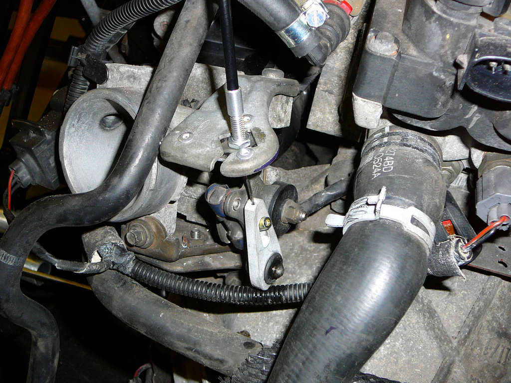
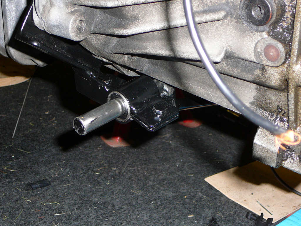
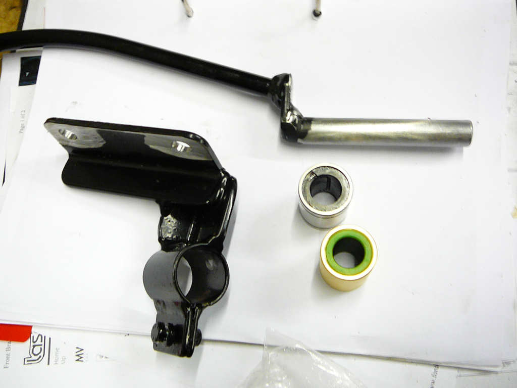
Here's a couple of photos of the modified gearbox switch as mentioned yesterday. As you can see, it now clears the chassis rail and oil no longer pours out of the bottom of the gearbox.
I've also fitted the gear link transfer arm that moves the gearshift rod on the Fiesta gearbox back around to the front of the engine. I'm waiting for the MK2 Astra gear linkage to arrive so I can get it modified and recouple the gearshift lever to the gearbox.
The bodykit and windscreen are on order from Stingray/Sylva and should be ready to collect at the end of October. While I was on the phone, I asked if Ali had any experience of fitting GRP seats to the Mojo. Apparently, it has been done but deails are sketchy. I've been looking at some nice seats from JK Composites which look great and are reasonably priced. I emailled them earlier today with a request for dimensions so that I could assess any potential issues with the seatbelt holes. Their reply was that these holes can be put anywhere I want (within reason) and that they had just completed fitting a pair of these seats into another Mojo! The seat they ended up fitting isn't on their website and is their part number N4042. Here's a photo...
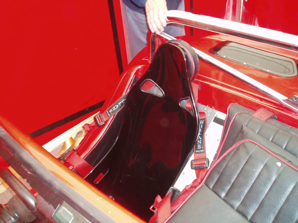
I was originally looking at N3942 which is 10mm narrower across the base. However, every extra helps since the Mojo is not a particularly large car to start with! I don't need to order these seats just yet but at least now I know what I'll be after when the time comes...
I've also received my K&N air filter and a clutch reservoir from a Honda Goldwing today. I'm just about to go on a hunt for an array of pipes and then I can do some plumbing.
![]()
Well another week has nearly passed! I've spent the last few days looking into the wiring loom from the Fiesta and laying out where I think the cable runs will be. I've chopped out several parts of the loom, hopefully without destroying anything important! The modifications so far are:
1 - Remove the airbag loom connector, wiring, and fuse.
2 - Remove the heater connectors, wiring, and fuse.
3 - Disconnect the rear window demister wiring from the back and relocate to the dashboard. This will now be used to control the windscreen demister.
4 - Remove the interior lighting fixtures, wiring, and switches. Door switches may not be much use without any doors!
5 - Remove the wiring for the optional electric seats.
The passenger compartment fusebox is now down to 12 fuses and 4 relays. The plastic casing around this is a bit on the large side and I may now transfer this over to a smaller fuse block, and mount the relays separately? I'm still trying to decide where to mount the fusebox but it's a bit tricky without the bodyshell because I've got no idea how much clearance I've got!
The hose-hunt from last week was successful: The first couple of scrapyards I tried either didn't want to know or didn't understand what I was after - the typical conversation went something like this:
me: Hello - I'm building a kit car and I'm after a variety of 32mm rubber hoses to do some coolant pipework. Can I come down and have alook around?
scrapyard: What car is is for?
me: Sylva Mojo SE. It's a kit car.
scrapyard: Never heard of it. Who's it made by? Is it an import?
me: No - it's a kit car and I'm building it in my workshop. The kit was supplied by Sylva Autokits.
scrapyard: We don't have any Sylva (silver?) cars here.
me: Ok look - I need to get coolant hoses from cars ike Fiestas, Golfs etc so that I can cut them around and fit them to my kit car. Can I come down and have a look around?
scrapyard: No public allowed in the yard. Tell me what you want and I'll see if we've got it.
me: 32mm rubber pipes.
scrapyard: What reg Fiesta?
me: Doesn't matter. I just need a variety. Could be from a Fiesta, Golf, Astra. Whatever.
scrapyard: Have you tried somewhere like Halfords?
me: Yes, but they supply new hoses and they're quite expensive. I was hoping to get something a little cheaper from a salvage yard.
scrapyard: We don't do hoses.
me: huh?
And so it went on. Until I found C&N auto dismantlers whose conversation was more like:
me: Hello - I'm building a kit car and I'm after a variety of 32mm rubber hoses to do some coolant pipework. Can I come down and have alook around?
scrapyard: Yep. Bring your own tools. We're open til 4 tonight.
me: <shock>
A few hours later and I had this lot for £15.
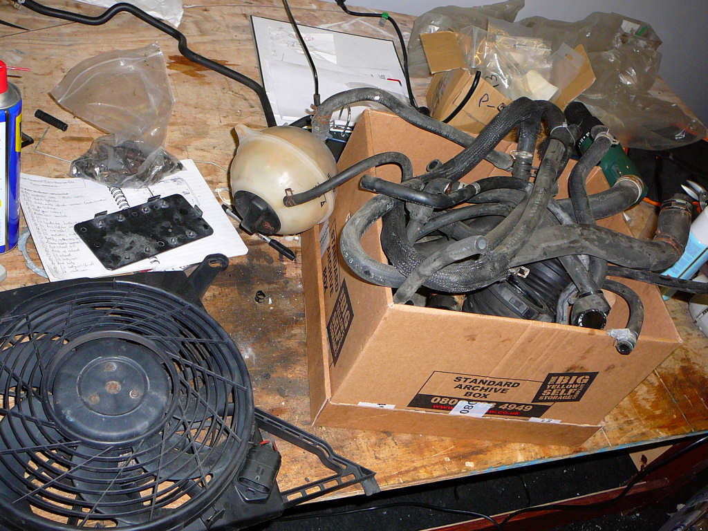
The keen-eyed among you will note that there's also a header tank from a Golf and a cooling fan from a Chavalier. The fan appears to be fairly thin so may be modifiable to fit into the Mojo. It it doesn't work then I'll just have to get a proper Pacet fan or similar but if i can avoid the extra cost then I will. The lesson here is that there are some great scrpayards around still and that it's worth hunting around for one. Also, there are evidently some that have unfortunately gone all 'Health and Safety' and do not want to be dealing with the public anymore which is a shame. I know who will get my business in the future!
Moving on: The Astra gear linkage has arrived and has now been cut to length. I'll ask Pete at work to weld the ends on for me as I still don't have a welder!
I've also been speaking to JP about exhausts. I removed the spring from the rear shock absorber and did a static bump test on the driveshaft that looked like it would clash with the catalytic converter. It did. JP had suggested that a Focus 1600 exhaust manifold would fit and would work well with the catalytic silencer from Sylva, or that the driveshaft could be changed back to the MK4 Fiesta version with some modification. I'm going to keep these 2 ideas back for a while because I'm hatching an idea to reuse what I've already got first and couple it to the cheaper non-cat silencer. If it doesn't work, then I can start looking for a 1600 Focus. I need to decide fairly quickly though as I'm hoping to pick up the silencer (cat or non-cat?) when I collect the bodywork from JP later this month. Incidentally - still no news regarding the brake master cylinder.
In order to get the clearance back between cat and driveshaft, the exhaust could be moved backward by sandwiching a spacer between the manifold and the block. Nobody seems to sell such a spacer/flange so I had a couple of options: Get an old manifold and grind the pipes off leaving just the flange, or machine a new flange out of block of aluminium/steel etc. Whilst trying to measure how thick the spacer would need to be, I realised that the same could be achieved by machining the mounting face of the manifold with a slight angle. This would have the effect of pushing to bottom of the catalytic converter away from the driveshaft, but shouldn't cause too many problems with the length of the existing studs etc. By jamming various sized drill bits between the manifold and the engine block, I've determined that the mounting face of the manifold needs to be cut at an angle that varies from 0mm removed at the bottom, to 4.5mm removed at the top. I'll also need to make a couple of spacers to support the bottom of the cat in it's new position. It may work, it may not. I'm not too fussed how it looks since it'll be covered with heatshields anyway so it's worth a try.
More importantly, every £1 I save now is another £1 of fuel to put in the car when it's finished!
![]()
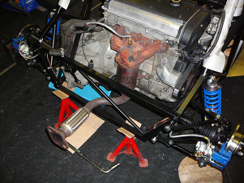
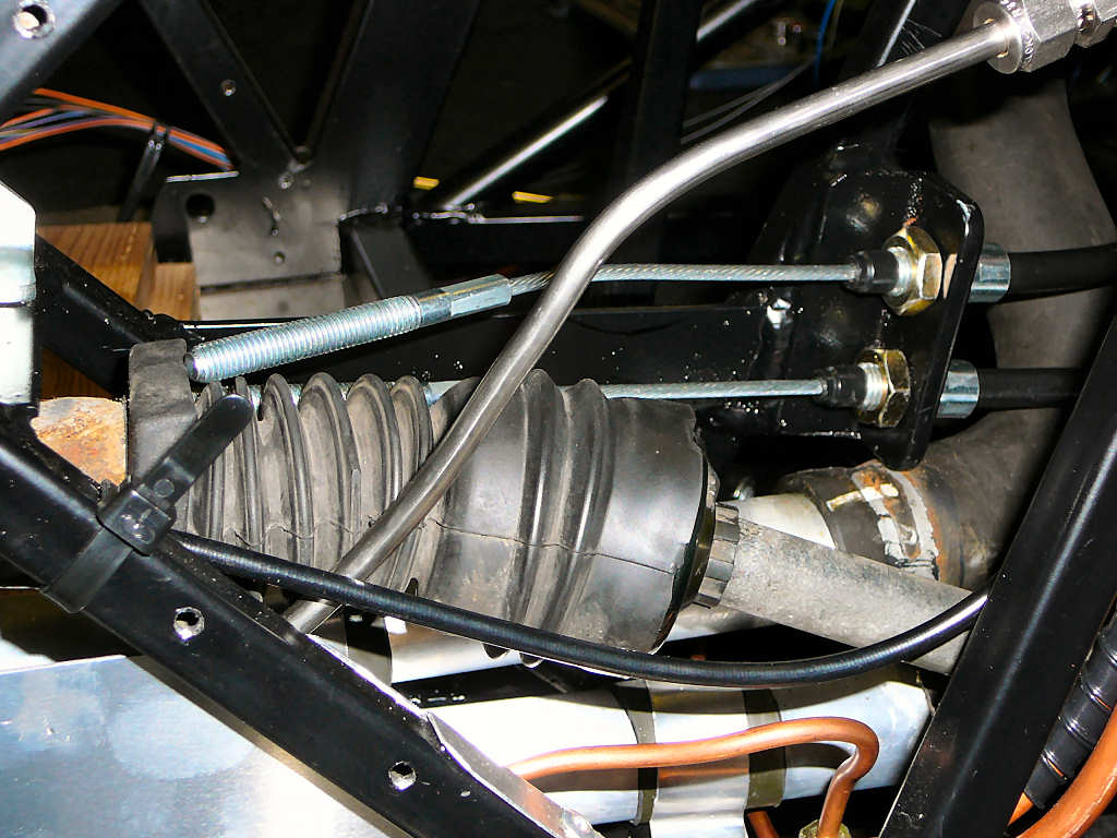
Well, I've got to thank Pete from work for doing a superb job on the exhaust manifold and the gear linkage for me! Here's a photo of the modified manifold showing the angled cut described above:
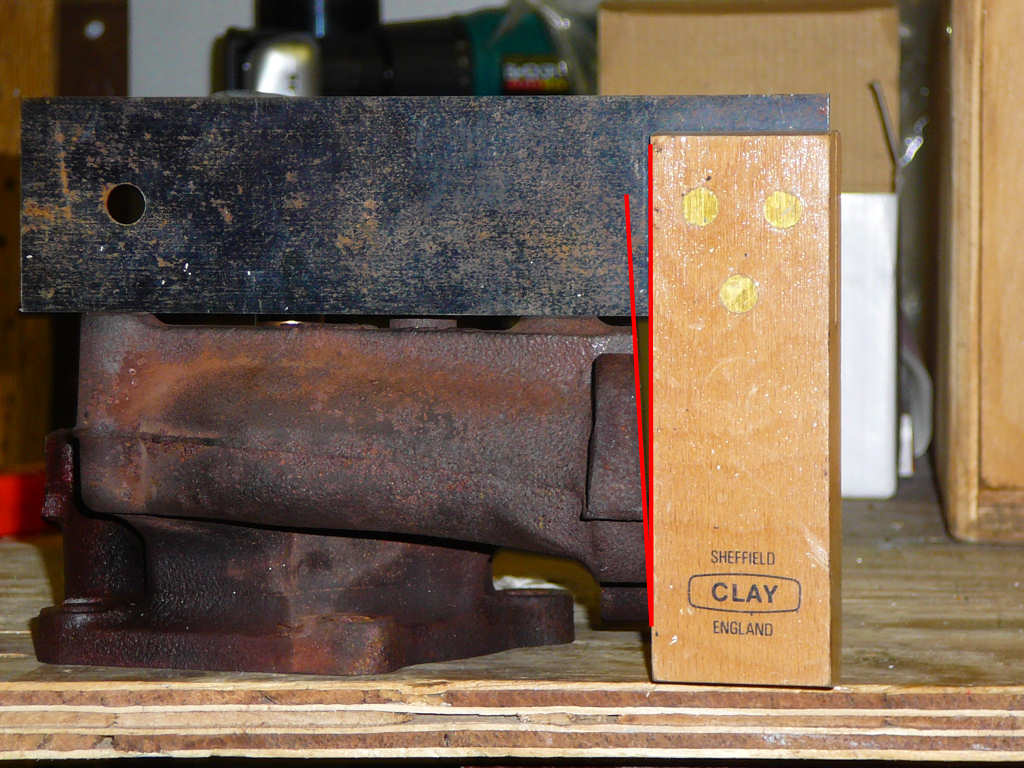
To reiterate, the angle is such that 0mm is removed from the bottom of the mounting face, and 4.5mm is removed from the top. The net result of this is that the bottom of the catalytic converter now misses the driveshaft by 30-40mm. I removed the shock and jacked the hub up as far as it would go (so that the driveshaft is nearly touching the chassis!) and there is still about 4-5mm of clearance. This is way more travel than would ever be experienced on the road and is significantly further than the bump stop on the shock, so I'm fairly confident that this will not pose a problem at SVA or in use. I've taken some other photos of the modified exhaust system for reference as below:
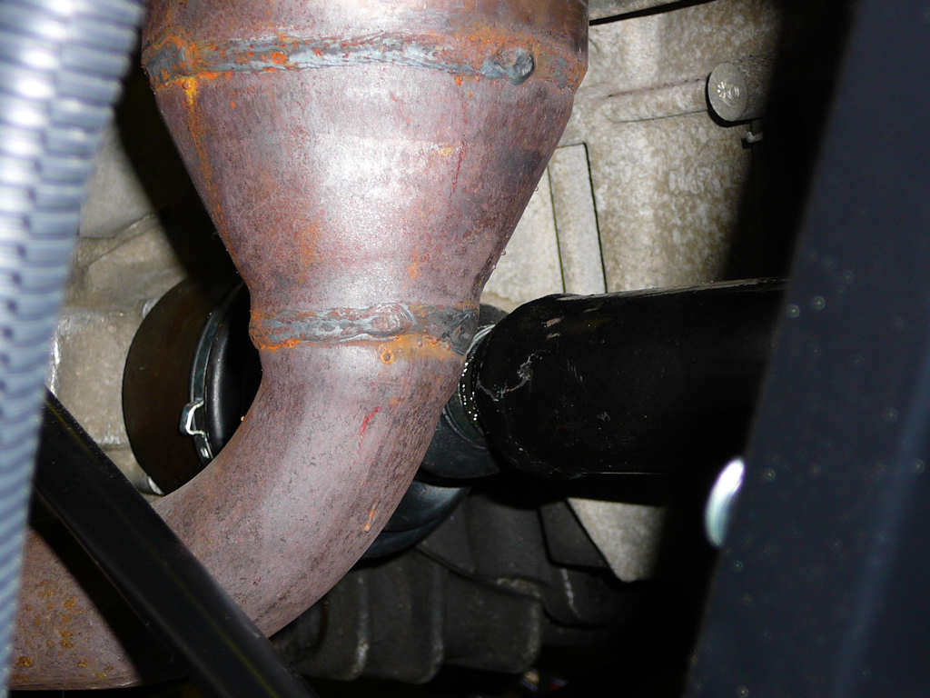
It's quite hard to see the spacing in these photos but it gives an overall idea of the layout so far. Because of the success of this modification, I've ordered the non-cat silencer from Jeremy today for collection early November. A quick calculation shows that this exhaust mod has probably cut about £300-400 off the total build! That will pay for the first years tax and insurance.
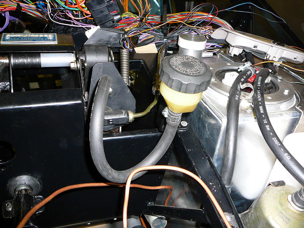
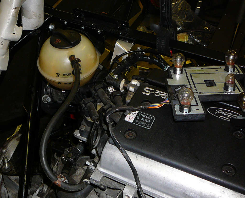
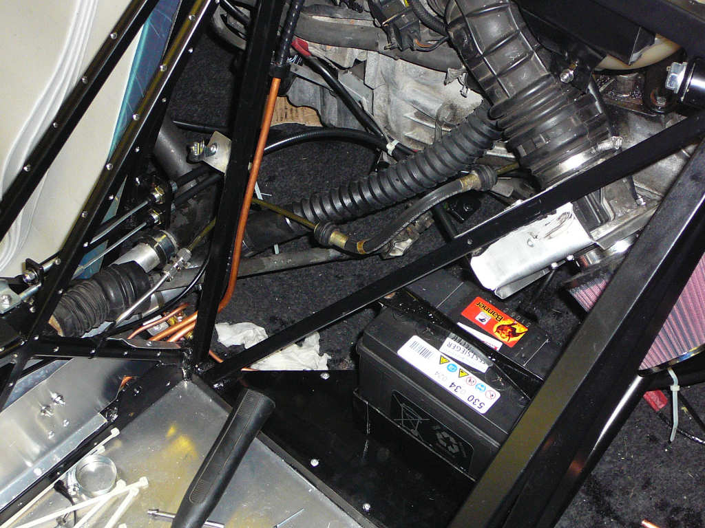
I've also fitted the clutch reservoir. It's a bit difficult to know if this is in the right position or not at the moment since I do not yet have the bodywork so check the clearances. I've spent some time looking at photos from other build sites and I think that this is a fairly good estimation of the required position. I can always change it if necessary. For reference, it's the brake reservoir from a Honda Goldwing motorcycle and cost me the sum total of £3 from eBay.
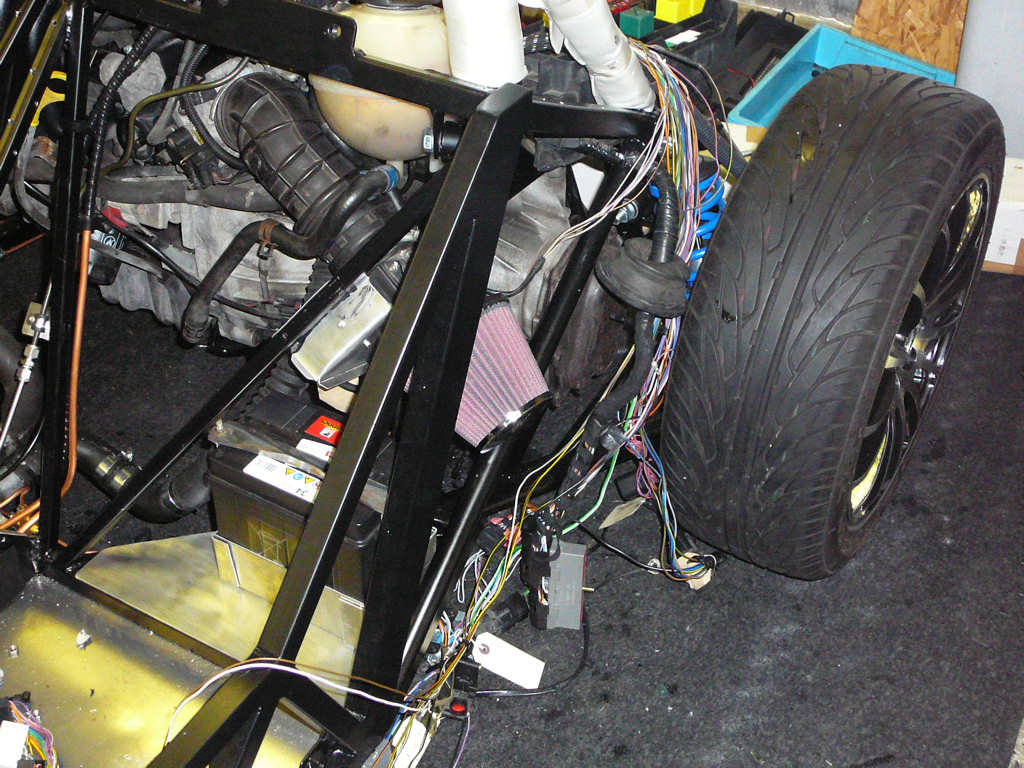
While on the subject of guessing bodywork clearances, I've made a bracket to hold the K&N air intake filter. I've replaced the Ford air hose with a part from a BMW (I think...?) that I got from the scrapyard the other day. It allows the intake to fit neatly between the battery and the header tank although it does end up sticking outside the outline of the chassis somewhat. Again, from studying photos, I'm hopeful that this will end up poking into the side-pod by the rear wheel which will allow it to get plenty of cold air although I'll need to make up some sort of cover/shield to prevent dirt and spashes from the tyres.
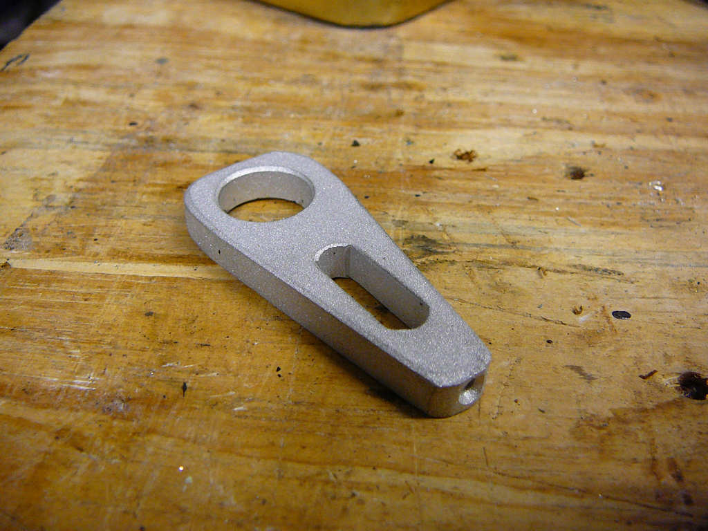
The other job I've been working on is the gear linkage. I'm aware that this is a job that needs to be done carefully if it is going to work well in the finished Mojo. Unfortunately, I've had no end of problems trying to get the linear bearing to do it's job properly! I work for a company that specialises in precision mechanical assemblies so I'm well used to working with bearings etc (the last job I did had to maintain positional stability within 20nm for 72hrs. That's 0.00002mm!) The problem was that the transfer rod shaft that fits underneath the gearbox was slightly too small for the linear bearing which resulted in a fair amount of 'slop'. This meant that when the complete gear linkage was assembled and lined up, the first couple of gear changes would be smooth but then they would start to get notchy. I know that overtightening the linear bearing can crush it and cause the rod to bind but the bolt that clamps the bearing was only fingertight for this test. The problem was that the rod would occasionally 'grab' inside the bearing which would gouge lumps out of the shaft. In an ideal world, this shaft would be made of silver steel, or be hardened but it's just plain mild steel. I polished the gouges out of the shaft, rechecked the alignment and tried again with the same result. Time for a re-think...
I spoke to Pete and Richard at work today and we all agreed that there had to be a better way of achieving the function of this bearing. Again, I must thank both of these guys for helping me with this project! Their combined engineering knowledge and experience has been absolutely vital! I must also admit that I was always a little worried about the mention of gaffer tape in the build manual and I was keen to resolve this potential problem at the same time. The solution that was devised was to replace the linear bearing with a part that did not apply a point load onto the shaft. Moments (seemingly) later, Richard and his lathe have produced this!
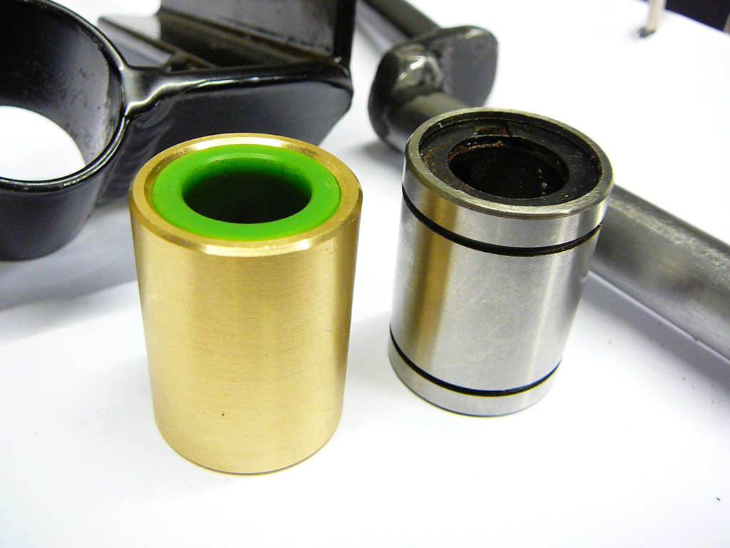
The one on the left is the new part, and the one on the right is the original bearing. The new part consists of a brass sleeve around a NyOil core (oil impregnated nylon). We have used this material before as a bearing surface in our products at work and it is well known for it's use in this kind of application.

Since the contct surface is now effectively a solid lump of plastic, there is less chance for debris and dust to enter and ruin the bearing which should promote long life with less adjustment. I've refitted the bush and the gear change is much improved although I still need to spend some time getting it a bit smoother. There's quite a bit of flex in the UJ's of the Astra gear linkage when moving from 4th to 3rd gear. This action puts the gear linkage into compression which makes everything want to fold up on itself because it is not all in a straight line. I'll post more as things progress...
I've recently ordered an OBD interface to allow me to connect the ECU to my laptop. This isn't to do any form of tuning (although it might be possible later with the Ford ECU?). This is so that I can check that everything is working correctly as I start the engine and to help me check the electrics. The OBD (On Board Diagnostics) is the thing that the garage charges you £85 to do when you have a problem with a production car, and it allows quite specific data to be gathered regarding any form of fault that has been detected. More importantly it allows the real-time monitoring of a large number fo variables such as oil pressure, fuel pressure, temperature, speed, tacho, air temperature, throttle position, manifold pressure etc etc and these may become useful for a cunning dashboard design that I've got in mind. Once again, in line with my way of thinking: Why go and spend a load of money of dials and gauges, and then worry about plumbing and wiring senders into position when the ECU can give you all of the information you need down a pair of wires? Of course I'll need to make up some form of display and controller to actually show any of this information but than again, you are on the MadInventions website! Watch this space... Incidentally, the OBD interface cost around £15 including postage. In order to keep SVA happy, I'll probably fit something like a Vapor computer for now and do this post-SVA.
The final thing to mention is that I've been looking into handbrake cables again. I've had quotes of anywhere between £96 to £140 for a pair of these cables which did not seem at all sensible to me! I spoke to Jeremy earlier today and we thought about how to modify a Sierra or Fiesta cable to see if one could be reused since they are only around £20-30. I set this aside as a possible option and then started to look at trailer brake cables as suggested previously by Michael B. He had mentioned some Ifor Williams cables as being suitable for the Rally Design Hydromec calipers but I could not find any information to verify that they would fit the Sierra calipers. However, I did locate these people - TrailerTek - who do exactly what is required for £12 each. Yes - that's £12 each including VAT! I've ordered a pair of the 1200mm cables to see if there is a catch. Something has got to be different to make them this cheap and the cynic in me says that it's probably quality that will suffer but if it's strong enough to stop a 750Kg trailer, it'll probably stop a 500Kg Mojo! I'll post some images when they arrive...
![]()
Well, the new handbrake cables have arrived and they look to be pretty good quality. The 'Sierra' ends are slightly larger than the original Ford parts, but that just seems to make fitting them a little easier!
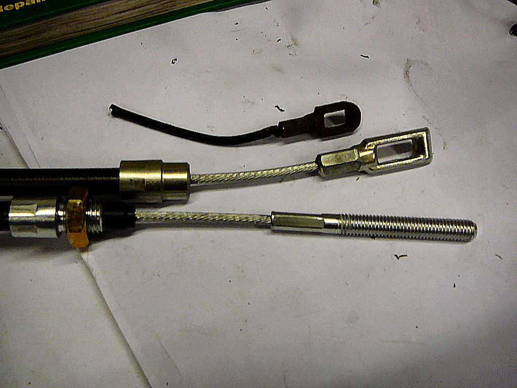
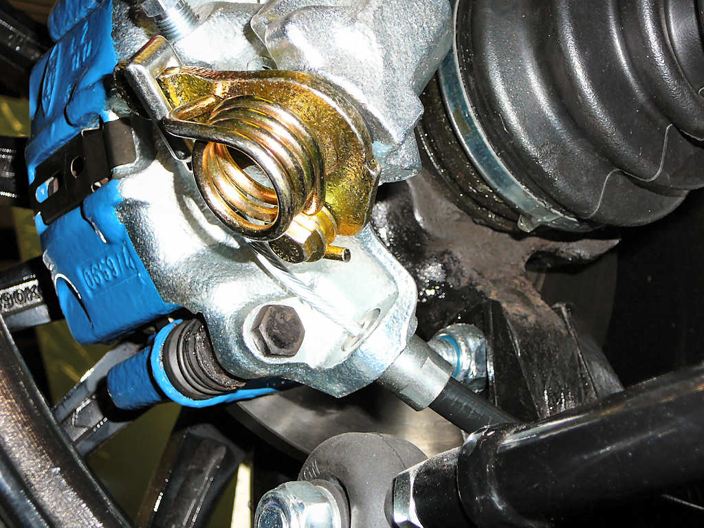
The bushes on the new cables are a perfect fit for the Sierra calipers. :-)
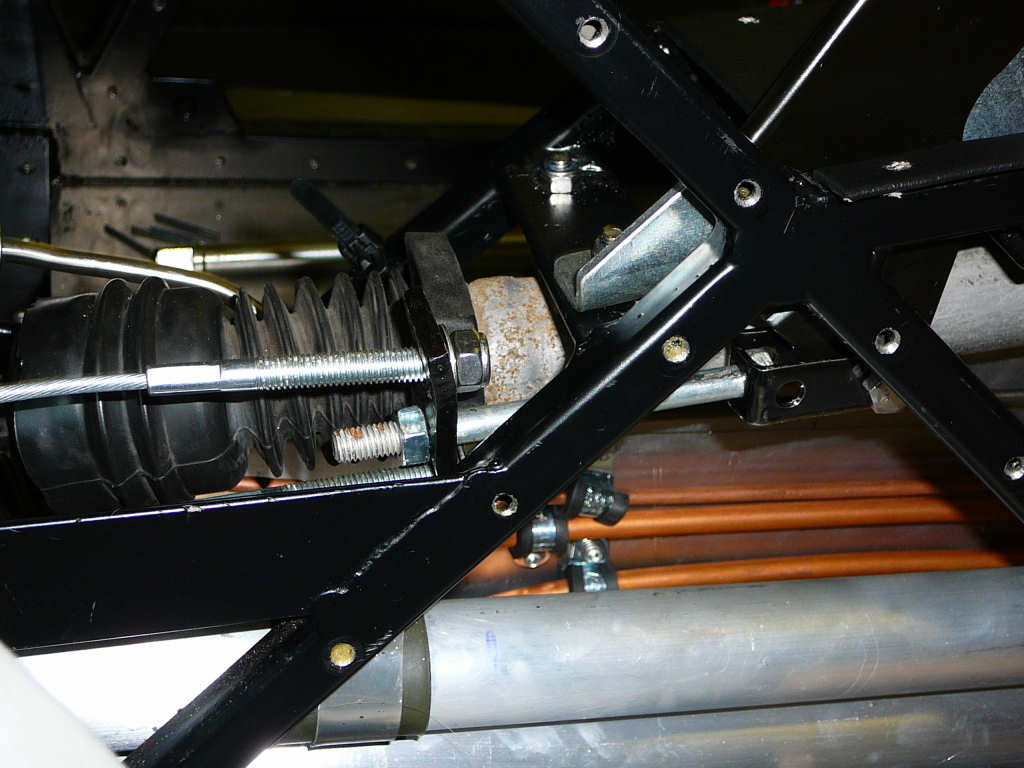
I chose a cable with a length of 1200mm which was based on some rather guesstimated measurements of the chassis. This has turned out to be about right, and has allowed for some fairly long sweeping bends in the cable which will help prolong the life of the cable. I'll probably make up a bracket or two to help support the cables along their length, as this will help stop them vibrating and fouling the gear linkage or touching the engine block.
As for the other end - The cable comes with threaded ends and nuts which fit perfectly into the Mojo chassis. You can just about make out the parts in this photo - space is getting a little tight at this end of the tunnel!
I will now need to make up some sort of mechanism to join these two cable ends to the handbrake lever, and ensure it gives enough articulation to keep Mr SVA happy.
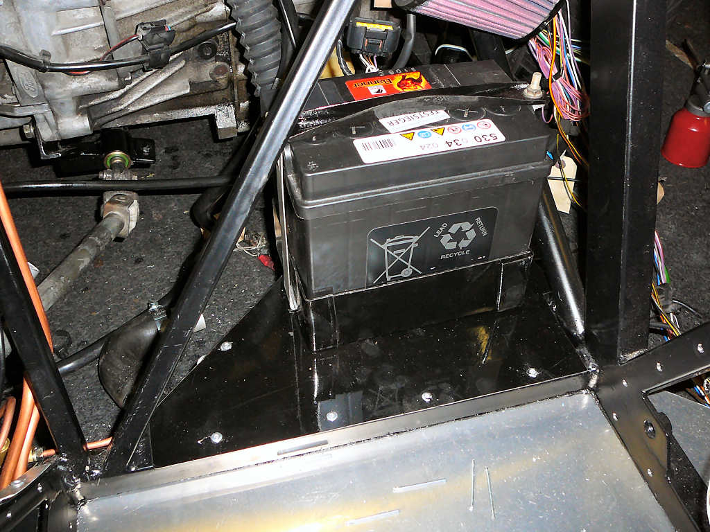
The other job I have done is to mount the battery. I made up a plate to support the weight and folded up a small box to stop the battery sliding around. The original battery box from the Fiesta was cannibalised to make the strap to hold the battery down. The whole thing is held together with TigerSeal, 4.8mm rivets and a few M6 nuts and bolts. I've put some 3mm thick closed cell foam in the bottom of the box to help stop rattles etc and gave the whole thing a quick blast of black hammerite to pretty it up a little. I'm going to cut an access panel in the passenger seat-back to get to this area for later maintenance, and the drivers side will also have an access panel cut into it.
Oh, and I've just realised that it's just gone 2 months since i started the build. Time flies when you're having fun!
![]()
It's been a while since the last update... The build has reached one of those lulls that seem to happen to almost every build! The list of dependencies has been hampering progress somewhat:
- Can't fit the radiator until I've got the radiator fan
- Can't fit the radiator and fan until I've got the body to check clearances
- Can't route the wiring until I've got the body to check clearances
- Can't fit the rear fusebox until I can check clearances to bodywork and exhaust
- Need to get new fuseholders for the front fusebox (Fiesta fusebox is enormous!)
- Water or electric heaters? Need to check clearances...
etc etc!
Anyway - Payday was on the 24th and I'm picking up the body, dashboard, windscreen and exhaust from Jeremy next week so there should be a burst of activity during early November!
In the meantime, I've been doing some of the smaller jobs on my list that have been lurking around for a while.
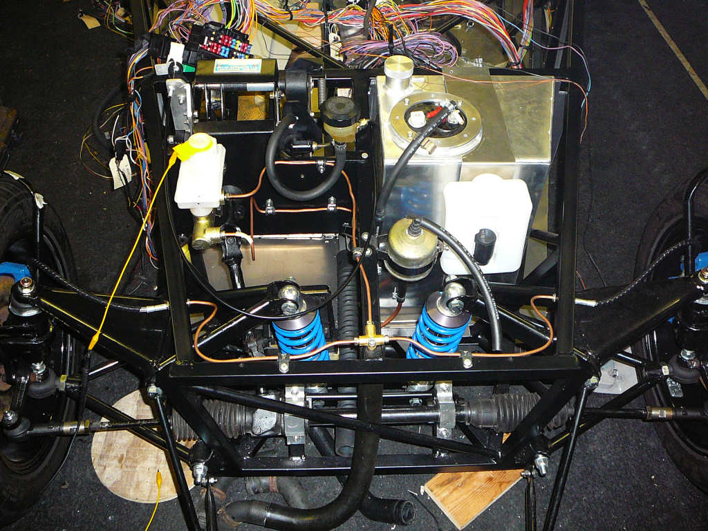
Firstly, I've fitted the header tank, This is from a VW Golf and is mounted to a rear crossmember using a simple folded bracket. I need to work out a way to plumb this into the coolant pipes... Car Builder Solutions do a rather nice 32mm/16mm aluminium t-piece that would do the job but it's £20 so I'm still looking for alternatives.
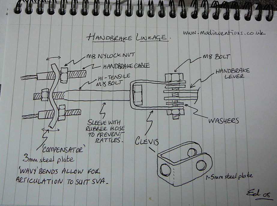
I've also made up the handbrake linkages. The handbrake lever is attached to a simple clevis by a M8 hi-tensile bolt. The clevis is just a piece of folded 1.5mm steel plate with 3 holes in it: 1 on each side for the handbrake lever bolt, and one at the back to transfer the motion to the compensator. A long bolt attaches the clevis to the compensator plate which is just a piece of 3mm steel plate with 3 more hols in it. The plate has been bent into a 'wavy' shape to increase the amount of articulation provided.
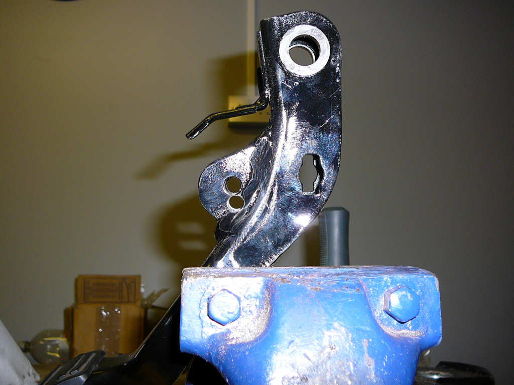
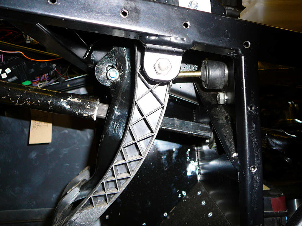
In order to progress with the handbrakes, I first need to finish the brakes. The brake master cylinder arrived from on Saturday morning (thanks Jeremy!) and was duly bolted into place. As mentioned by other builders, there is an alignment issue with the actuator rod of the bmc: The holes in the modified brake pedal are a little too high and cause the rod to jam against the top of the cylinder when the brake pedal is pushed hard. The easy way around this is to drill some new holes into the brake pedal in a slightly lower position. Since I am also a bit short, I would like the pedals to be quite high so I also moved the mounting holes forward as well. This has the effect of lining up all of the pedals nicely.
Once this is all fitted back into place, the next job is to bleed the brakes. For this I opted for the old fashioned 'persuade the wife to sit in the car and press the pedals' routine which worked quite well! In order to make the process as idiot proof as possible, I attached a multimeter to the brake fluid level switch so that we wouldn't have to keep too close an eye on the levels. It took quite a while to get rid of most of the air but then the system started to respond. After we got out as much air as we could, we pumped up the system again and blocked the pedal down with a length of wood. This was then left overnight, with the final bleed being done the next day. the pedal is now hard after 2 or 3 pumps so I'm fairly sure that all of the air is out. I'll check it again before the first drive though! Thankfully, there were no leaks anywhere on the system although I still managed to get covered in brake fluid somehow.... <sigh>
I had to re-route a couple of the brake lines in order to get rid of any inadvertant high points that became air pockets, and to make sure that everything flowed 'up-hill' to allow all of the air to collect somewhere that it could be bled from.
The clutch also needed bleeding and was next on the list. This took ages to get all of the air out and again involved re-routing the pipes. Some perseverance later and we were rewarded with a biting point about half-way down the pedal travel. This is better than the clutch on my everyday car so everything was tightened up and the procedure declared a success. At this point, the wife was released from the confines of the Mojo and returned to the relative warmth of the house to defrost!
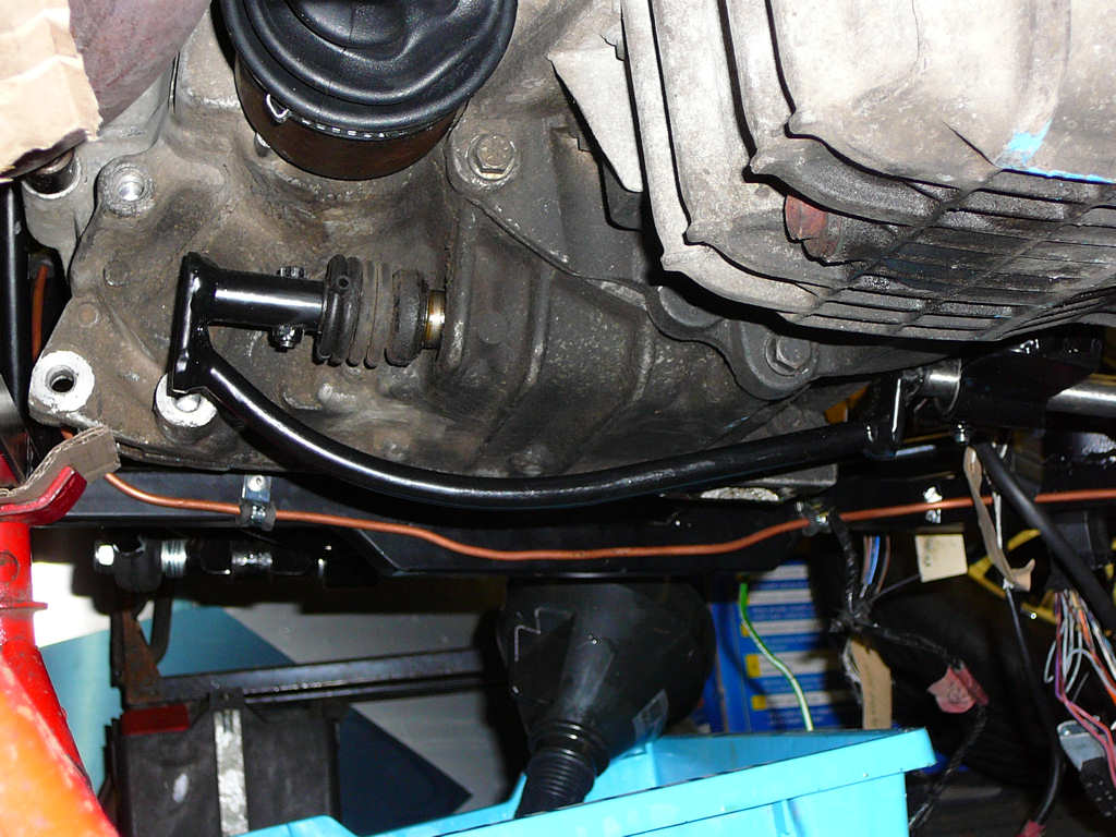
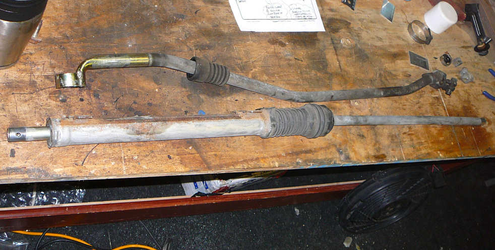
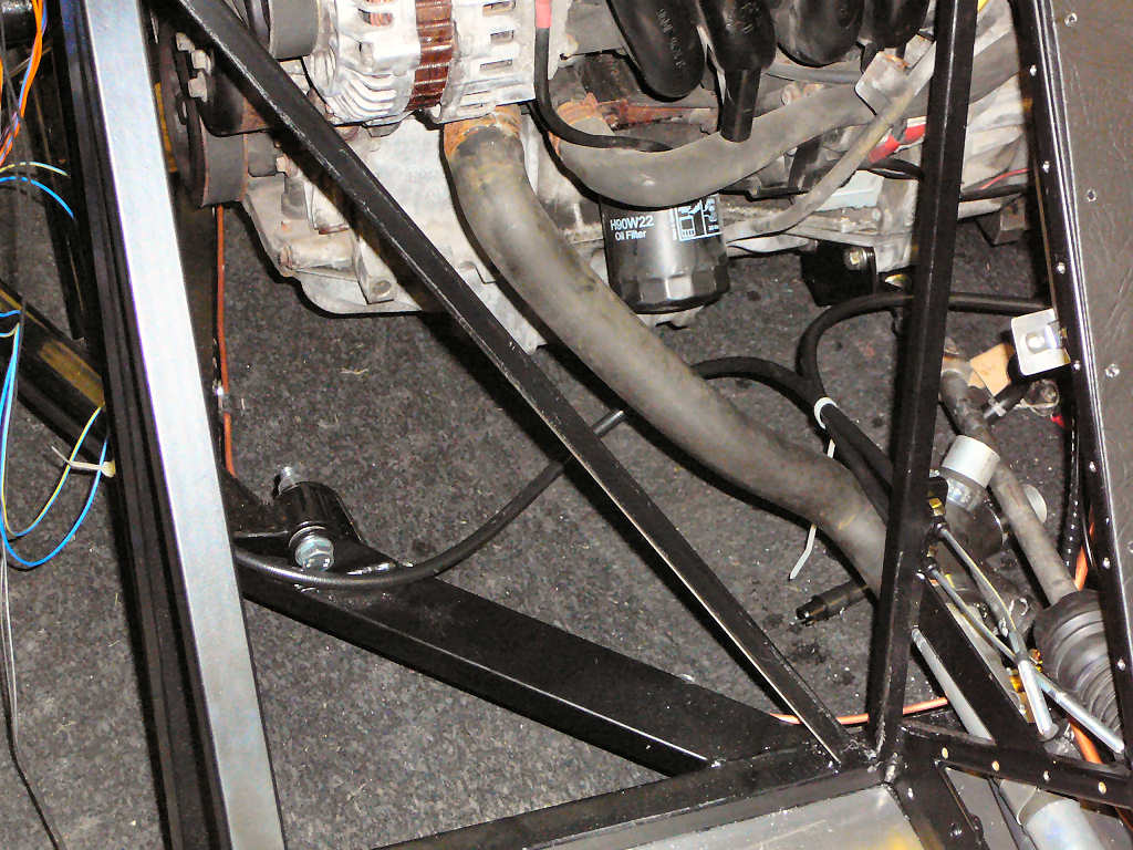
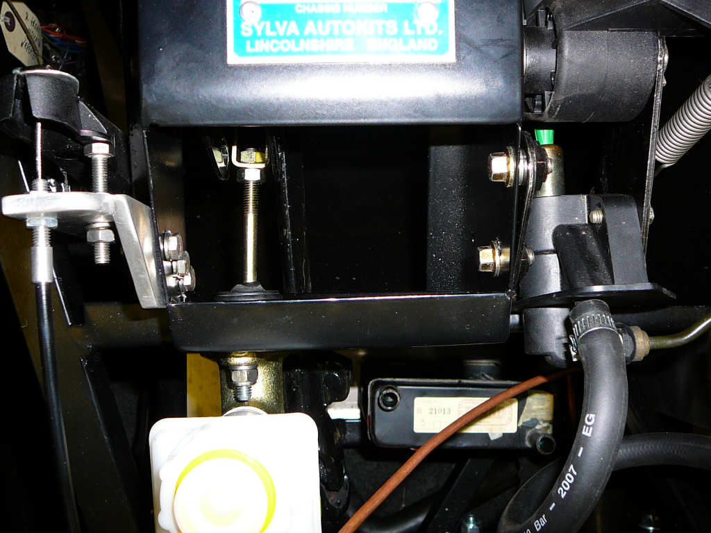
Here are some photos of the new pipe locations. I need to add some p-clips to hold everyhting in place.
The last thing I've done recently is to replace the gearbox oil with some fresh synthetic 75W-90 which should help inthe long run. For such a small gearbox, it sure does take a lot to fill it! The Haynes manual states that the level should be 10-15mm under the bottom of the filler/breather hole, and that this should take approx 2.8 litres. Well, 3 litres have gone in so far, and the level is about 80mm under the hole. And no, there isn't a leak anywhere!
![]()