


![]()
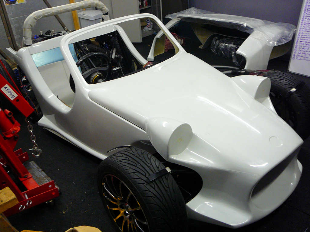
Well November has got off to a roaring start... the bodyshell is here!
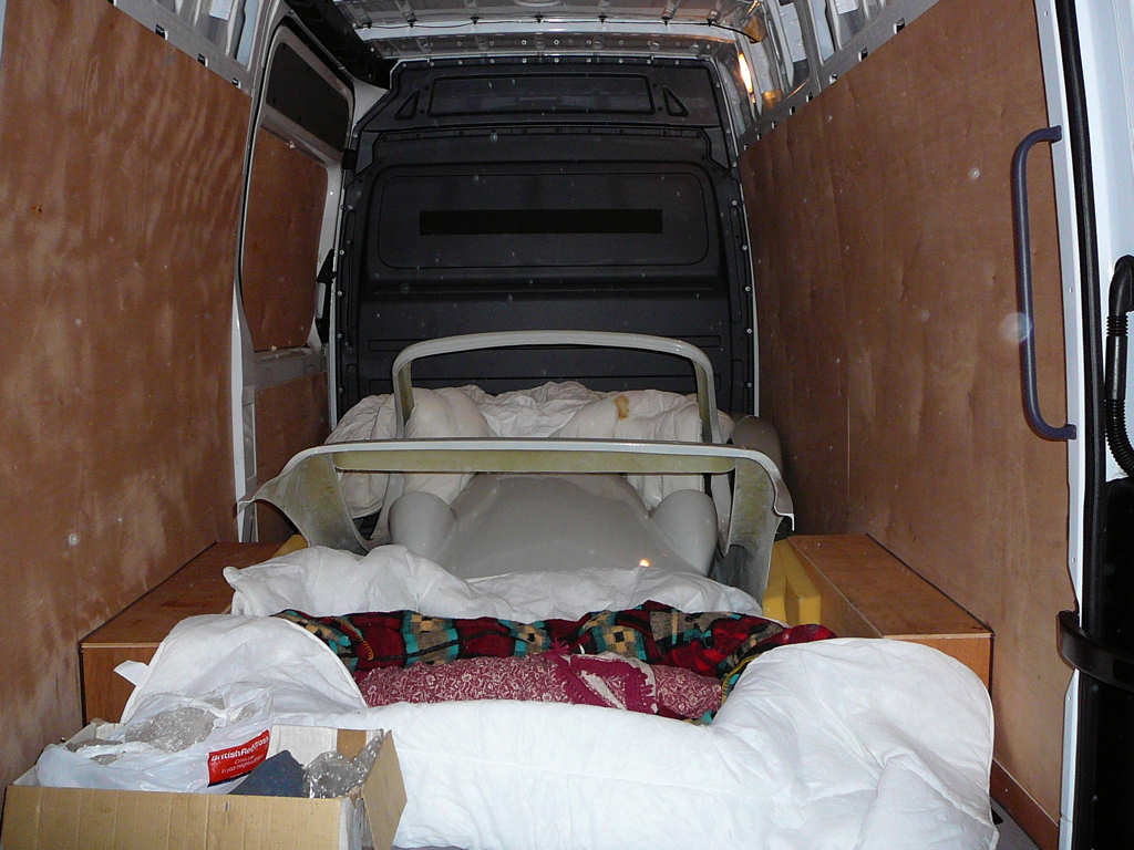
On Monday, we hired another van (Mercedes Sprinter from Global Self Drive) and headed up to Jeremy's workshop in Horncastle. We spent an hour or so chatting about all sorts of Mojo related things such as lights etc, and loaded up the van with the bodyshell, dashboard, exhaust and windscreen. The drive back was taken rather carefully and we managed to get back and unload just as it was getting dark. Phew...
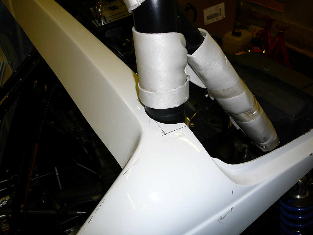
Of course, the first thing to do was to get the main body onto the chassis to see what it looked like! This meant cutting out part of the rear crossmember to allow the body to seat correctly around the rollbar. "Measure twice, cut once" everyone always says. I thought about this, and spent ages measuring where to cut the fibreglass, then gave up and resorted to my more usual procedure of "Measure once, cut once, then file to fit". A 50mm holesaw did the initial cut, and then a 50mm flap wheel sander in a drill provided the final shaping. In order to keep mess under control, I attached the workshop vac to the side of the drill to remove the fibreglass dust. This made for a relatively painless operation that only took a few minutes in the end.
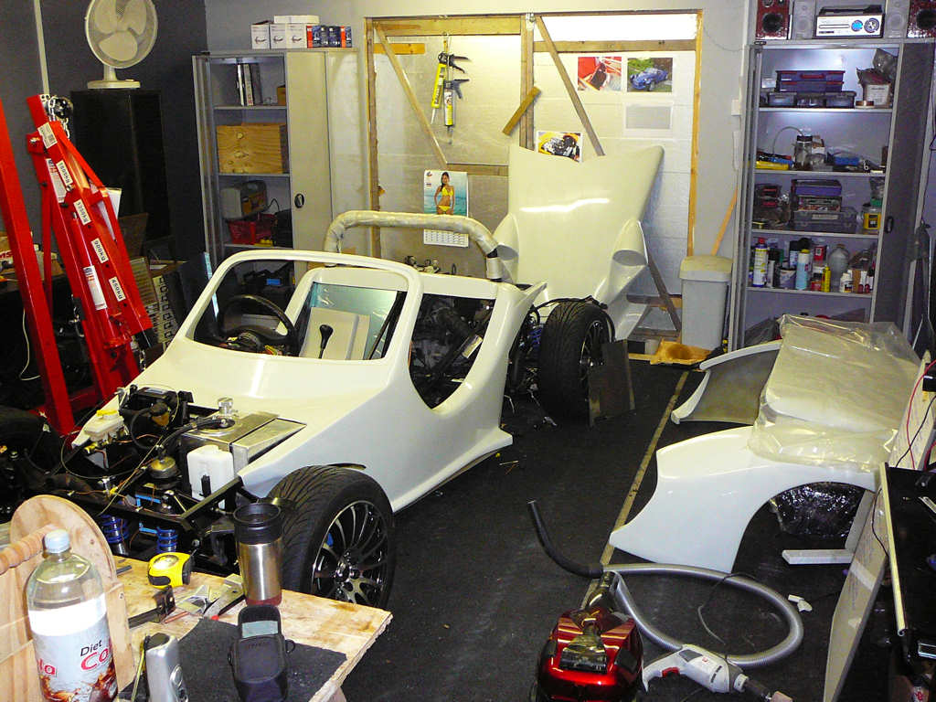
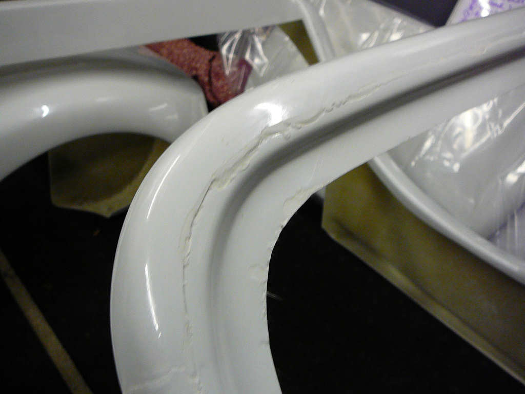
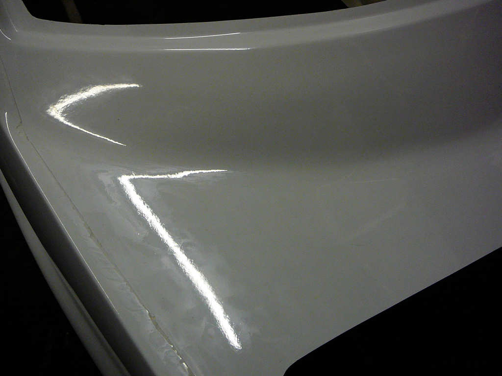
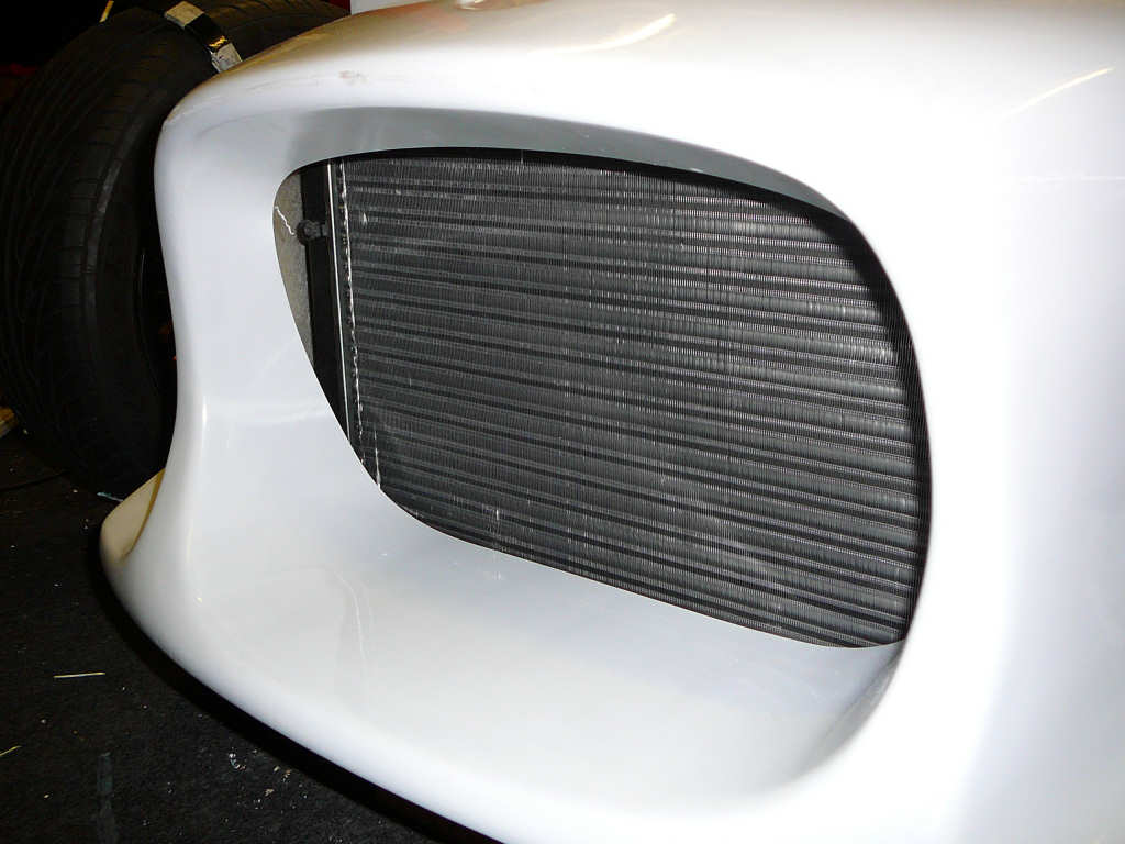
As you can see, the quality of the fibreglass is very good! There's a fair amount of touching up to do around the seam lines from the mould, but overall this shouldn't take too much effort (or make too much mess!). I was envisaging having to flat the entire body which would take a lot of elbow grease - thankfully, it now looks like the body is 90% ready for paint already! I need to go over the enitre shell with a fine-toothed comb and make good any parts that need attention but this shouldn't take too long.
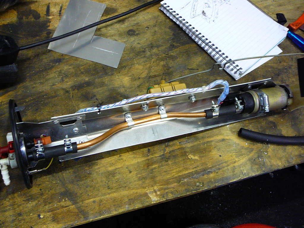
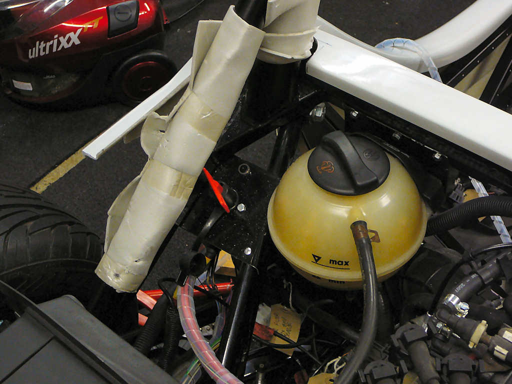
A length of the in-tank fuel hose was added to Monday's parts collection for me (Thanks Ali!) so I was able to get the fuel tank finished quickly.
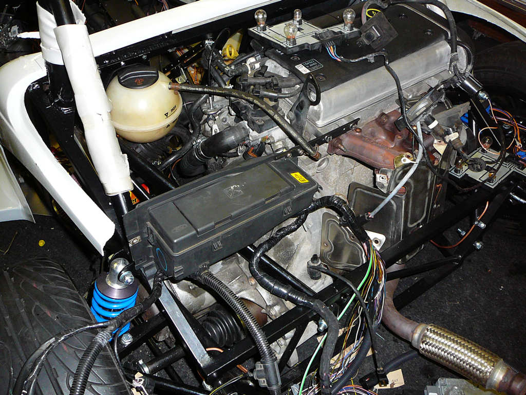
Now that the bodyshell is here, I can double check the clearances around some of the other parts to be fitted. One of these is the rear fusebox. Now knowing where I can and cannot route the wiring, the fusebox was fitted in a matter of minutes.
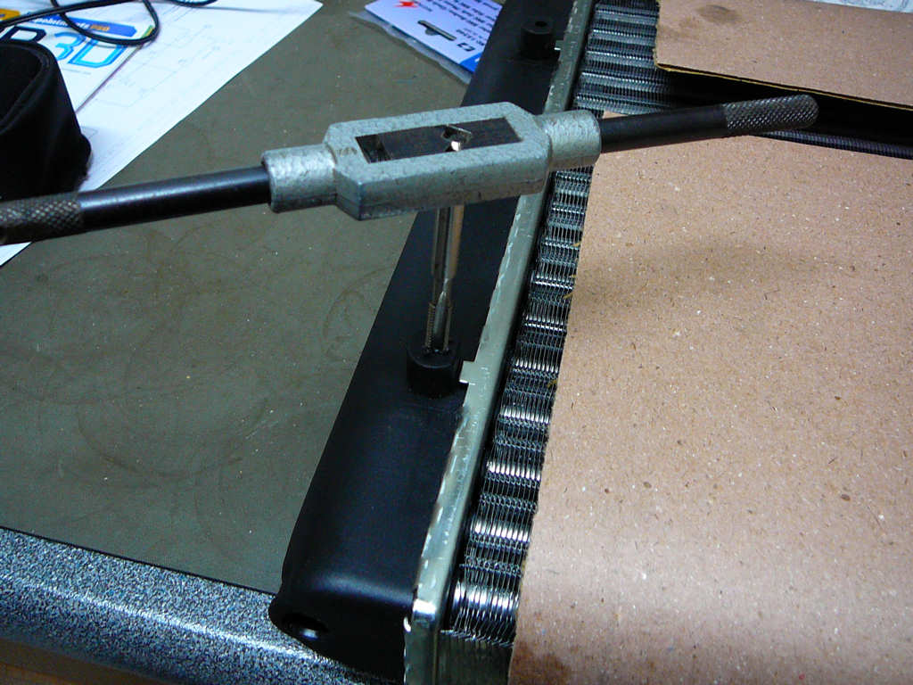
I can also now set about fitting the radiator. I'll be starting this in the next few days, but for now I've tapped the plastic mountings in the radiator to M6 to allow it to bolt directly to some yet to be made brackets.
Incidentally, the lights I was speaking to Jeremy about on Monday were the rear stop/tail and indicator units. These are 95mm diameter and are available from a number of manufacturers such as Wipac or Perei. A quick search on Google showed that these are called 'NAS' lights and are very popular in the off-road world and are often used as upgrades by the Land Rover fraternity. The Wipac units are reported to be of questionable quality sometimes, but you can't argue for £5 each! I'm yet to decide whether to go for the cheap bulb units or some nicer (but more expensive) LED versions.
Finally, my OBD interface has arrived from the USA. Unfortunately, it has arrived at work and I'm off all this week but I've got plenty to be getting on with for now anyway!
![]()
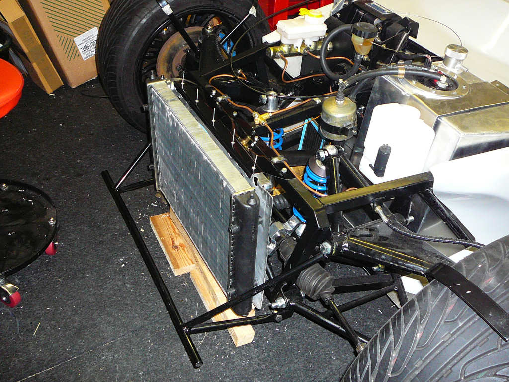
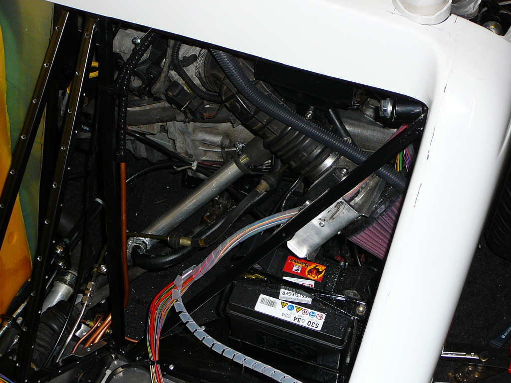
Spent a couple of days fitting the radiator which has required a fair bit of measuring, some trial-and-error, and the ususal dose of guesswork. However, the radiator is now fitted!
The first thing to do was to find a way of attaching the fan to the radiator, and then mounting the whole assembly to the chassis. The fan I am using didn't come with the through-core cable-tie type mountings that are often used, so I decided to make a single plate that would allow the fan to be bolted onto the 4 M6 bosses on the radiator. This plate has got a number of large holes drilled into it to aid airflow (note that they are now larger than shown in the photo below...) and folded top and bottom edges for rigidity.
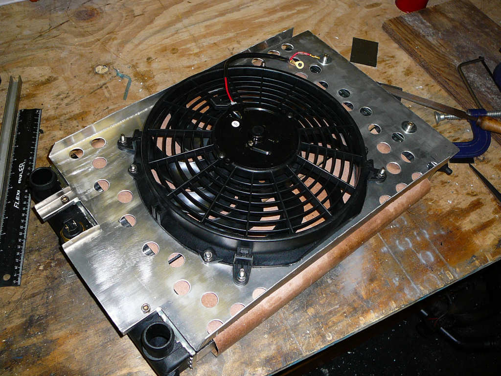
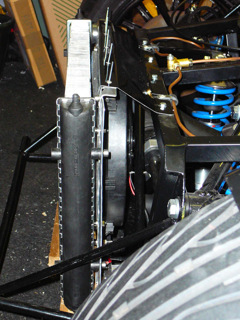
To mount this plate to the chassis, I've attached an aluminium bracket to the lower front edge of the chassis which supports most of the weight of the radiator and fan. The top edge of the plate is held onto the top crossmember of the chassis with another folded aluminium bracket. The longest part of this process is taken up by trying to ascertain exactly where the radiator can fit so that the pipework can be fitted but so that it doesn't foul the top of the 'bonnet'. In the end, the bottom of the radiator is in line with the centre of the bottom crossmember, and as far back as it can possibly go (remember to fit the pipes first!). The top can lean forwards due to the shape of the fibreglass moulding, but I've opted for a reasonably vertical installation.
I've used a thin strip of neoprene type rubber (good for 120°C ish) between the radiator core and the circumference of the fan to ensure that the fan pulls air through the radiator, not from the gap between the core and the plate! This should help the overall efficiency of the assembly.
![]()
First news of the day... The Mojo project has been sold to Matthew Beardshaw to make way for JPs new project based on the Riot. I'll post any more info here as it arrives...
Back to the build... Now that the radiator is fitted, it's about time I finished plumbing the cooling system together. I got another length of 32mm aluminium pipe from my favourite supplier (eBay) and used this to connect all the pieces together. Offcuts of 32mm rubber hose from the scrapyard were cut and used as joiners.
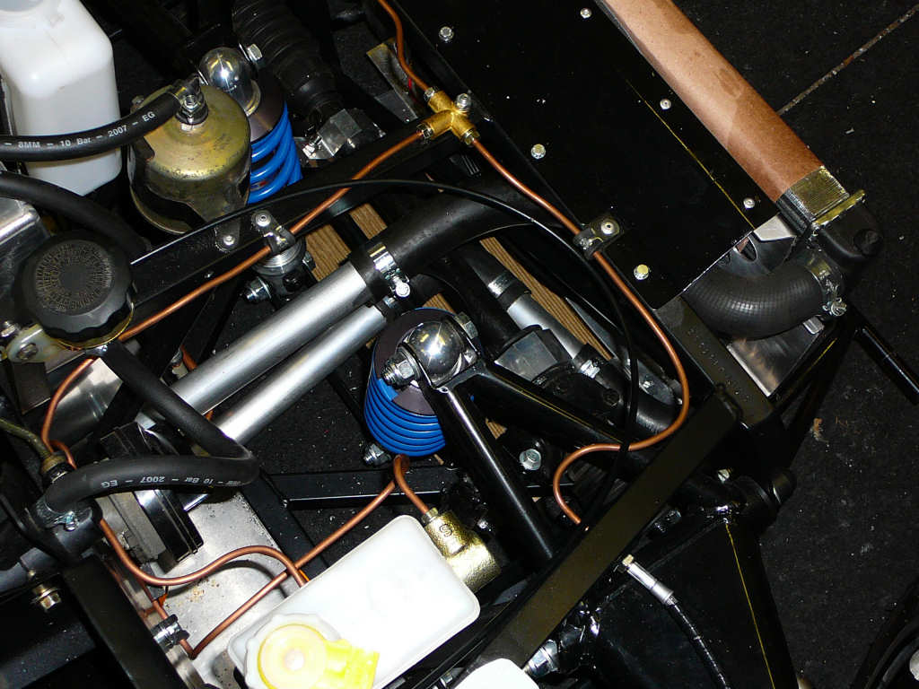
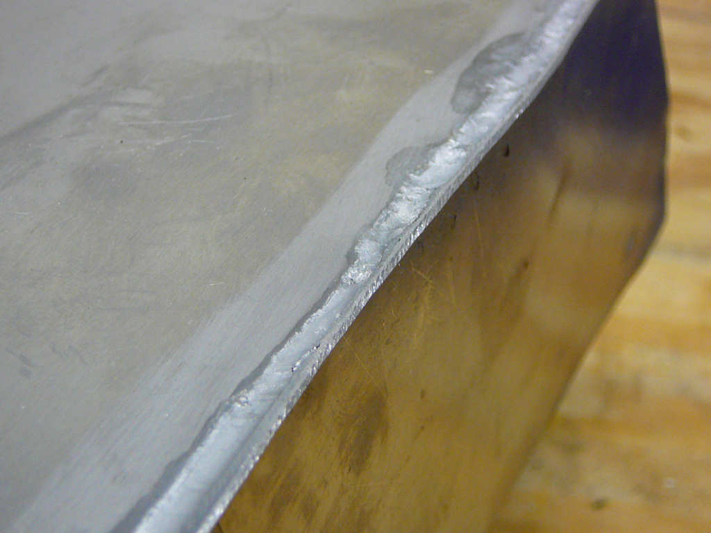
One of the problems I previously mentioned is the t-piece to connect the header tank. As you can just about see in the left picture, I've fabricated one of these by brazing a brass hose fitting onto the aluminium pipe. "Brazing you say? Onto aluminium? Preposterous". Well - no. I've used a product called 'DuraFix EasyWeld' from weld-uk which allows good joins to be achieved using nothing more than a blow torch. It comes in rod form and doesn't require any flux. You just heat up the material, remove the flame and then melt the rod into the join. Have a look on YouTube to see how easy it really is!
Anyhoo - the plumbing is complete and I now realise that I've picked the worst possible weekend to try and find any Antifreeze. There's about 3-4inches of snow outside, so filling the system and checking for leaks will just have to wait until it all thaws out a little bit...
In the meantime, I've made up a simple box to house the ECU, fuel inertia switch and the OBD reader (on board diagnostics...). The novelty hasn't worn off yet so I've used DuraFix to join the parts of the box. I could have used rivets, but a blow torch helps to heat up the workshop in a way that a rivet gun never will...
Several people have asked me how I fabricate various sheet metal parts on this build, so I've taken a few pictures of the process for this. Unfortunately, I forgot to take pictures regularly so there's a bit of a Blue Peter style 'Here's one I prepared earlier' feel to these, but it's better than nothing hopefully!
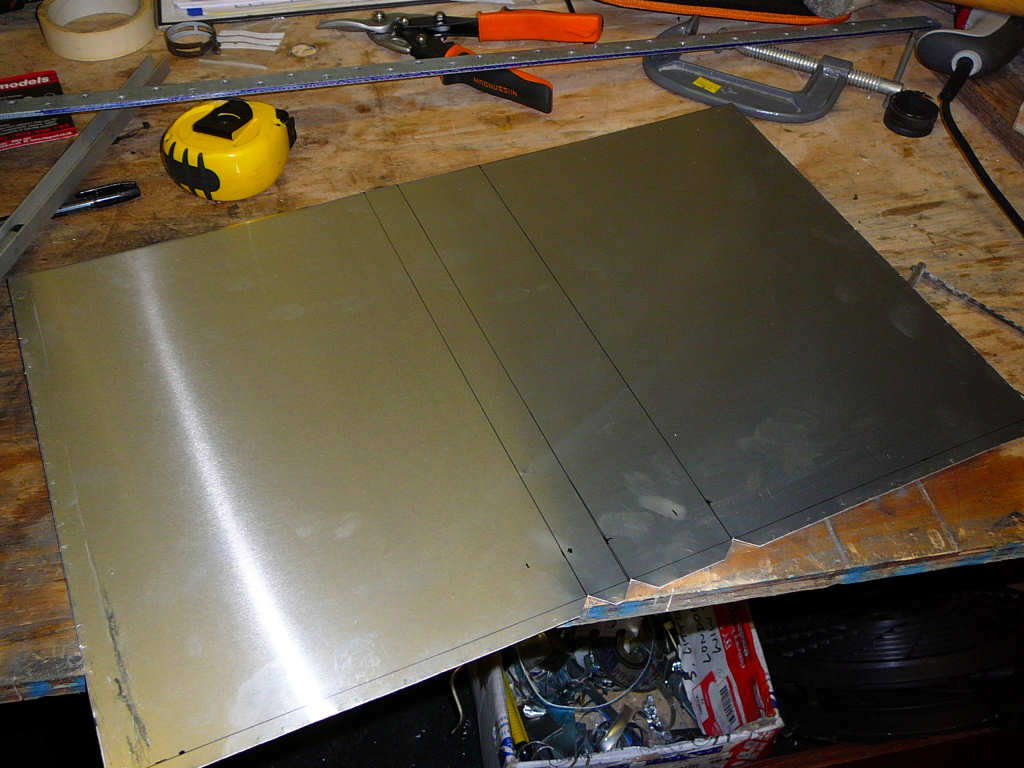
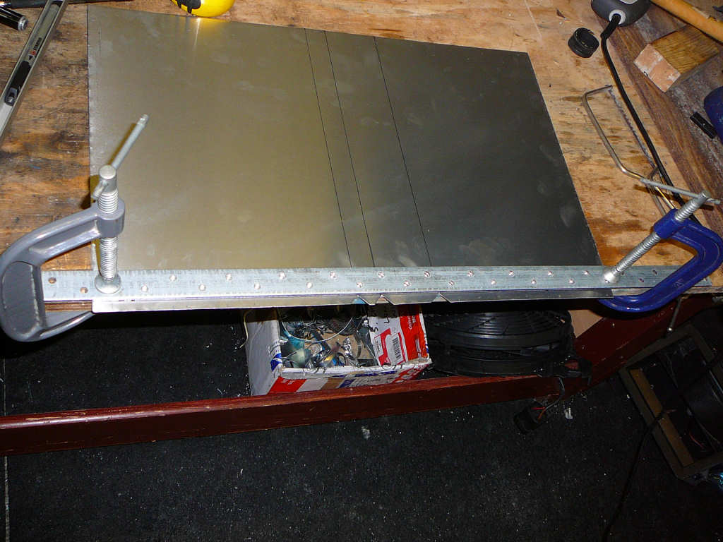
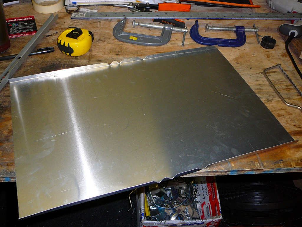
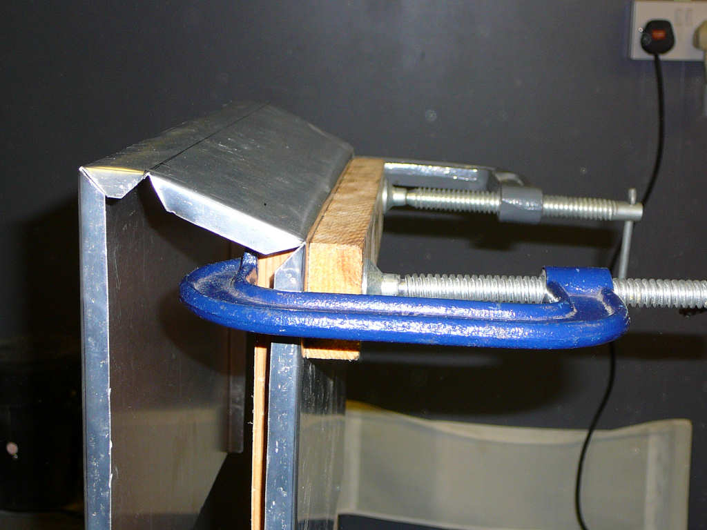
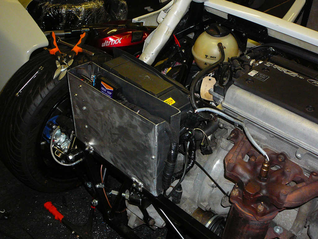
As you can see, it's a case of mark, cut, clamp, bend, join, fit. Or thereabouts. I've missed out some of the stages like 'shred knuckles, make coffee, swear' etc but these are kind of optional anyway. :-) I'll make a lid to fit onto this box, and then the ECU will be protected from dust and grit, and the aluminium will also help deflect some of the exhaust heat hopefully.
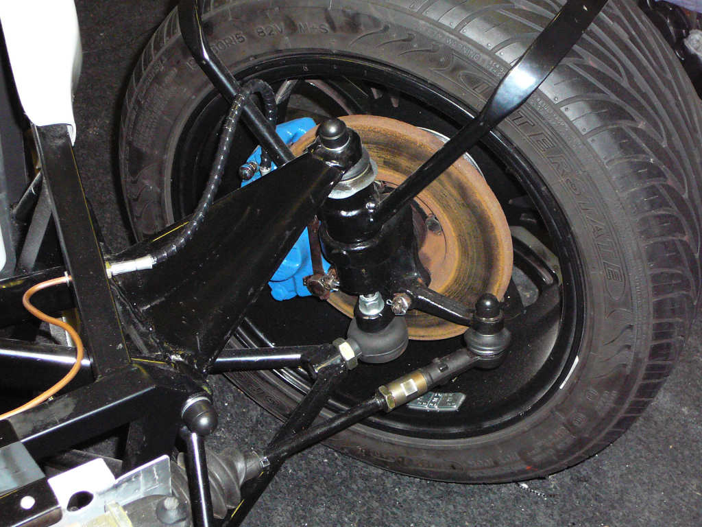
Another quick job that has been done is to fit the SVA nut covers.
I've also started to fit the dashboard. It's still a case of trying to work out the ideal position and then somehow clamp it into place so I can make the necessary brackets. After a while of doing this, I decided that this whas decidedly awkward and it would probably be easier to juggle some angry badgers whilst wearing oven gloves, so I've left this for now and I'll wait for some inspiration before continuing...
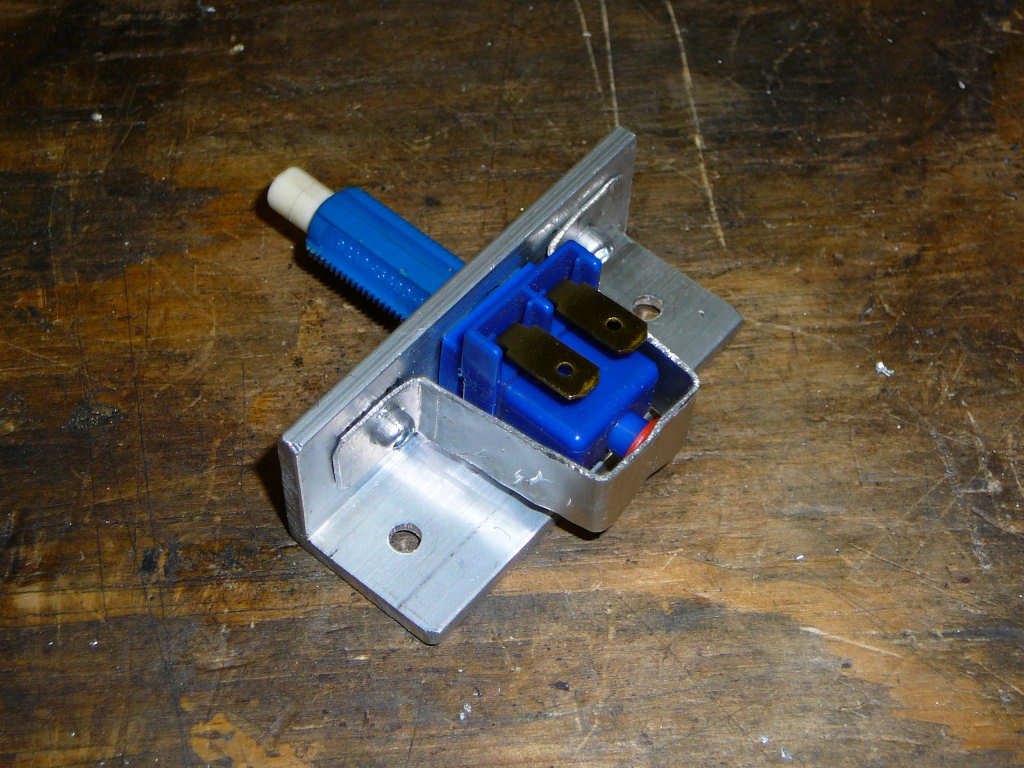
The brake pedal switch has now got a bracket which will be fitted to the chassis.
And the battery isolator has been fitted. I've put a small (2A) circuit breaker across the contacts so that the battery will always be connected to things like the ECU and the clock, but it will instantly trip if some low-life tries to start the car with the isolator active (or if I forget one day!). Even though the Fiesta immobiliser is still used, it'll probably help to have an isolator fitted.
One final thing I wanted to start work on is the seats. I quite like the look of the GRP seats from JK Composites, but these will cost around £300 including the upholstery and it's looking like the budget simply won't stretch to this at the moment. Therefore, I started thinking about making up some temporary seats to get through SVA and do for the time being. From looking at the Sylva seats from Intatrim, they look easy enough to copy since they are just foam on a plywood backing with some upholstery. The search for some suitable foam began and then I thought about trying to re-use yet another part of the Fiesta. It's got two pretty comfortable seats which only need to be made narrower to fit into the Mojo.
The first job is to remove the Ford covers and remove the foam from the seat framework. The suprisingly heavy steel frame has been put onto the recycle pile along with much of the rest of the Fiesta and will be weighed in for scrap later...
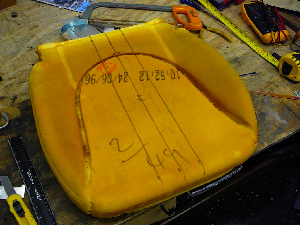
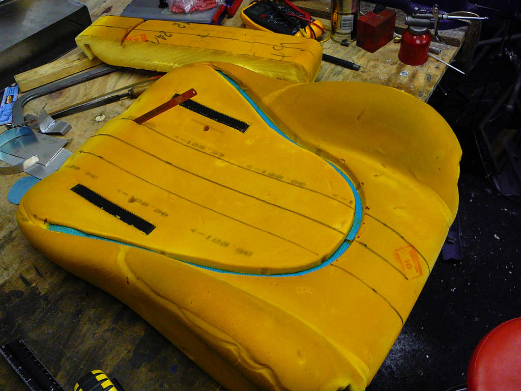
I measured them and determined that about 100mm needs to be removed from the overall width. To do this, I marked the centreline, and then two more lines 50mm away on each side. I cut along these lines with a hacksaw blade, and then stuck the two parts back together with EvoStick contact adhesive.
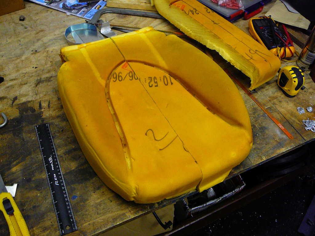
A little while later, these were test fitted into the Mojo and they fit quite well!
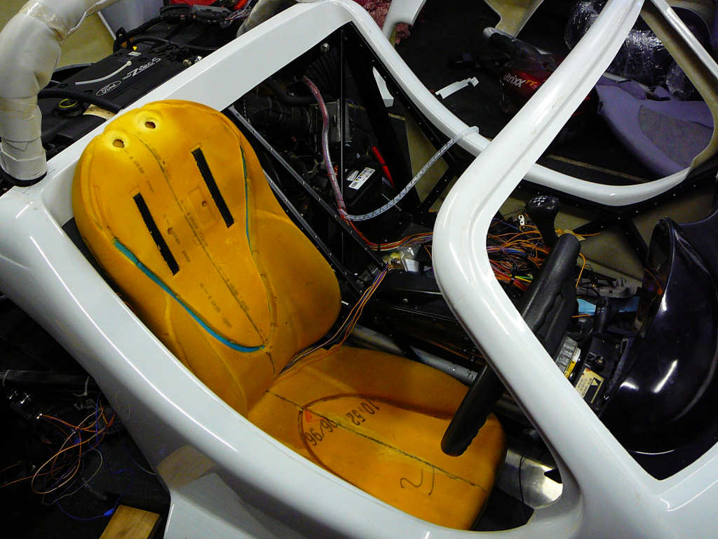
I still need to make the plywood backing for these and add a little more packing behind the foam (they're still a little bit low and I'm so short that I still need the backrest to move forward a couple of inches).
Once this is done, I'm planning to try and find some reasonable quality seat covers and modify them to fit. These will the be stretched over the foam and plywood and stapled into place. I'm not expecting them to look fantastic, but they'll be ok for now and save a lot of build cost. I can always replace them later after SVA and when funds allow!
![]()