

![]()
Whoa.... when did December arrive?!! What happened to the end of November? <sigh>
I've filled and bled to coolant system with no leaks (phew). For reference, I've used 3 litres of antifreeze and 4 litres of DI water which gives a 43% mix ratio. The Ford TIS manual states 40%, the Haynes manual is vague but errs towards 50%, and the back of the antifreeze bottle states 'no more than 60% mix'. I guess it's not that critical?
I've also made a little more progress on the seats.
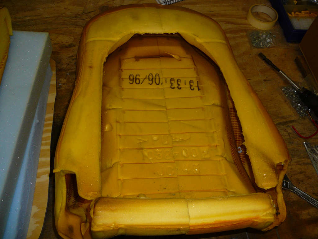
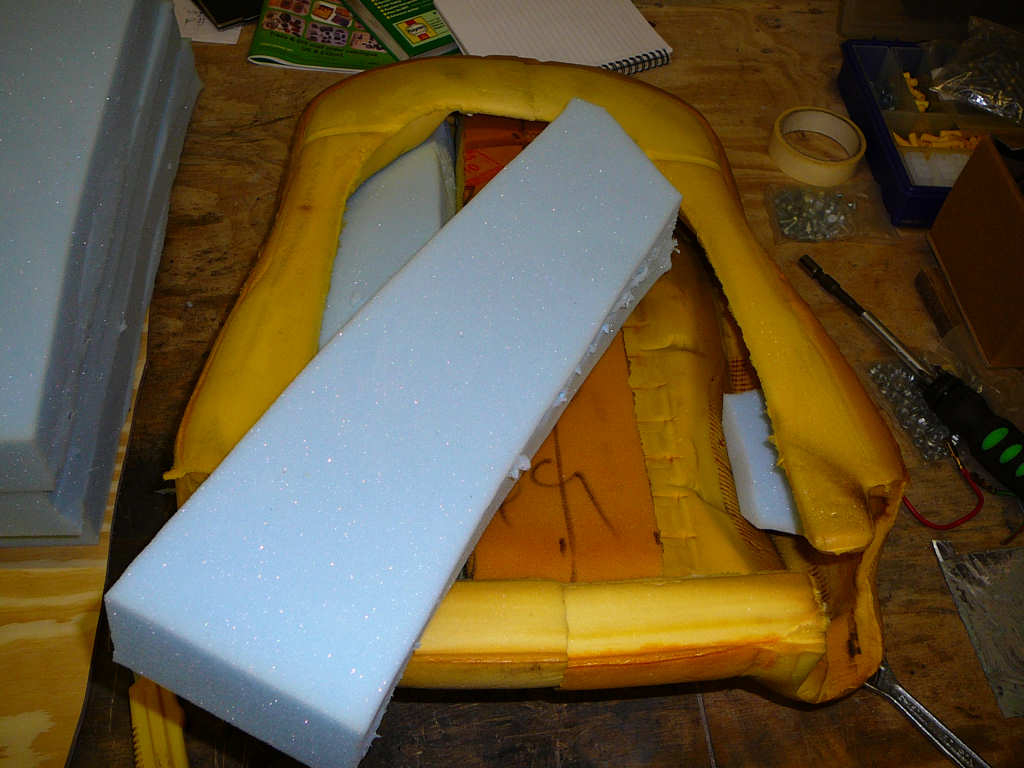
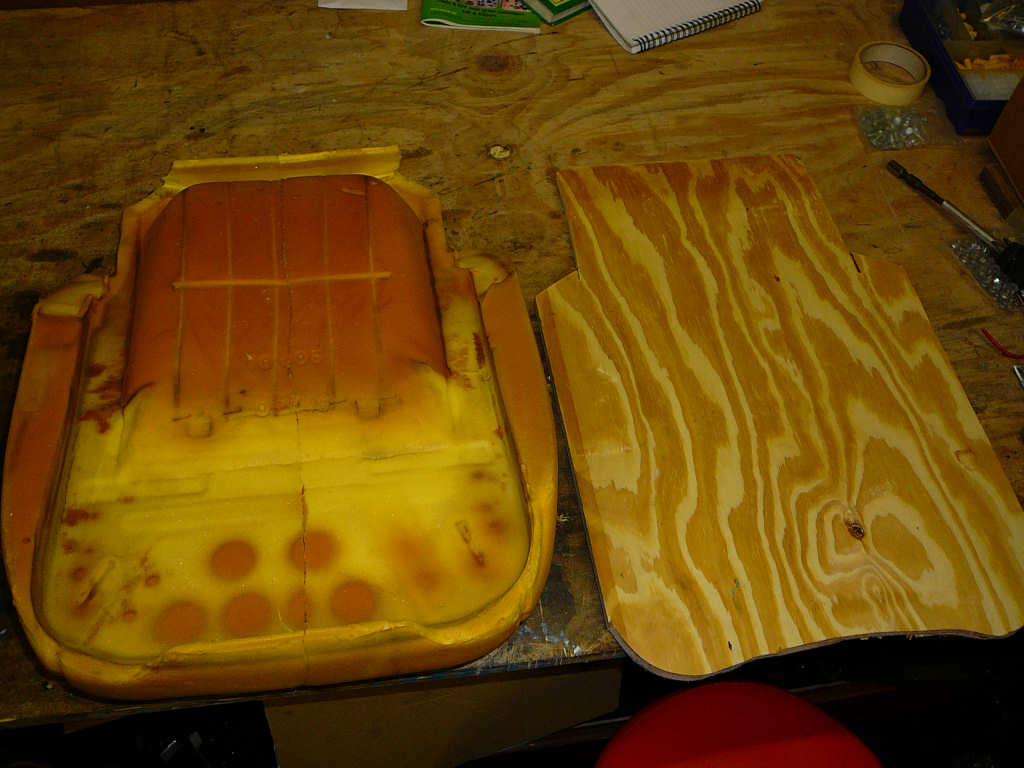
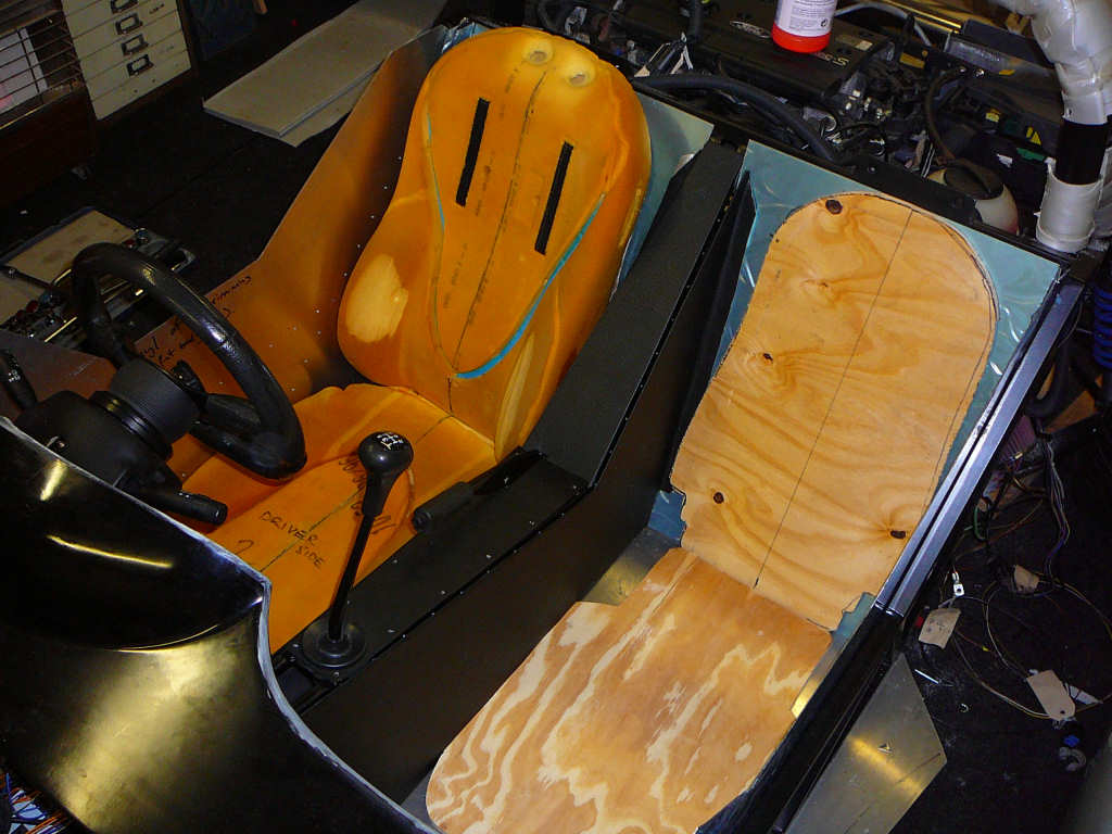
I've used some extra foam to fill the space in the back of the Fiesta seats to give a little more support. One part is the offcut from the seat base, and the blue parts are upholstery foam. These are just roughly cut to size and pushed into place.
I then moved on to cutting the seat backs and bases from plywood. Ideally, I would like to make these from GRP or aluminium but I'm intending to replace these seats fairly promplty when funds allow so I'm not too worried about it at the moment. The foam is then stuck to the boards using contact adhesive (I love the way the fumes make the workshop shimmer after a while...) and the seat covers will then be strectched over and secured to the boards using staples or something similar. Like I say - I'm not going for looks with these seats (although they shouldn't look too bad), but I would like them to be comfortable. And they certainly are! The extra foam in the backs and bases give them a reassuringly firm feel which holds you in place quite well. It remains to be seen how they perform on the road however... Total cost of these seats so far - about £25.
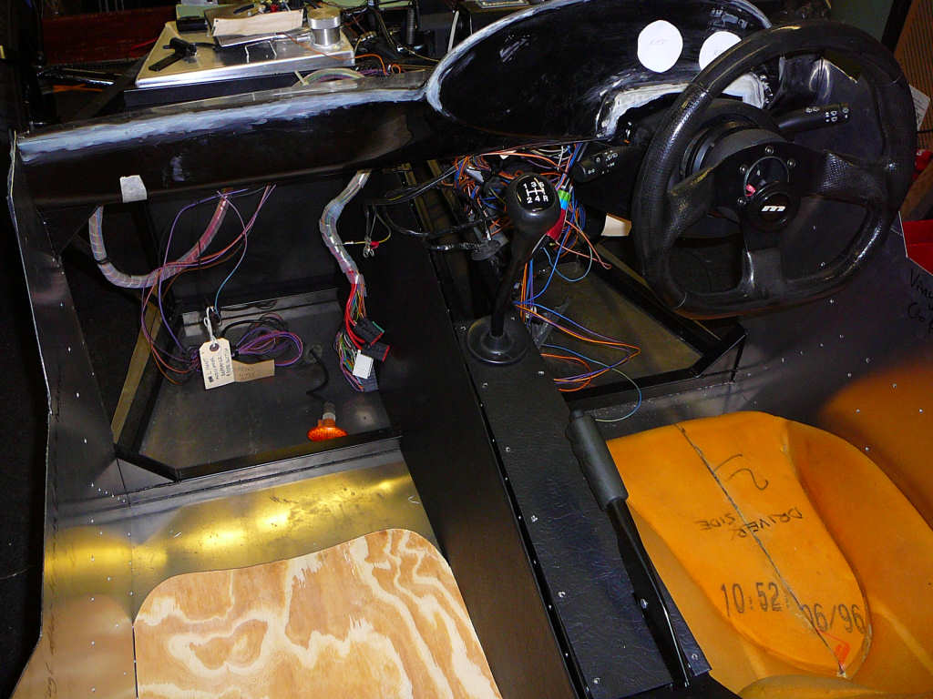
The wiring has also been started. After much deliberation regarding wiring routes, I've decided upon a solution that shouldn't lead to too many problems.
The main point to note here is that the 'cockpit' wiring loom runs along the angled braces behind the dashboard. This leaves the area immediately behind the dashboard free which should make fitting the wiper motor and demister a little easier hopefully. I've sourced several of the parts for the heater system already and more should be arriving soon. Watch this space...
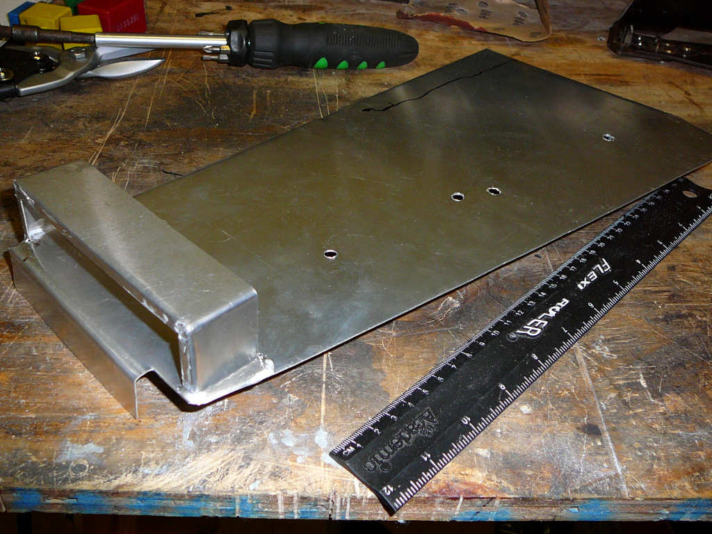
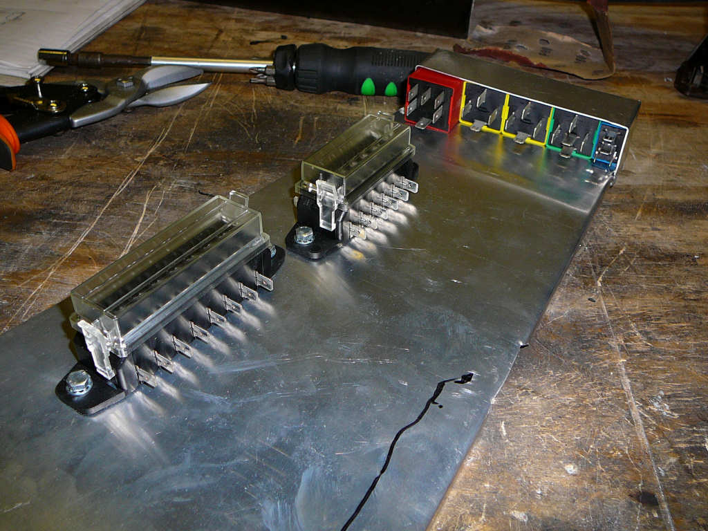
I needed to have somewhere to mount all of the existing fuses and relays from the Fiesta central fusebox and I decided that a plate to the top-right of the steering column would be good. Besides from being the natural place for the loom to run, it also allows reasonable access to the fuses once the bodywork is fitted in case I ever need to get to them in the future.
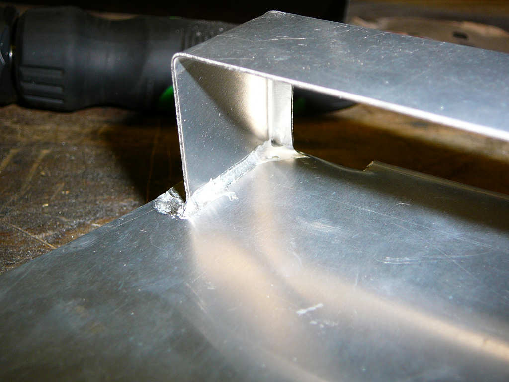
To make this plate, I cut out a piece of 1.2mm aluminium and bend the edges to form brackets. I then folded a simple U-bracket to hold all of the relays together and secured this to the plate using DuraFix.
To make the panel look better and to help reduce the possibility of shorts, I covered the panel in vinyl.
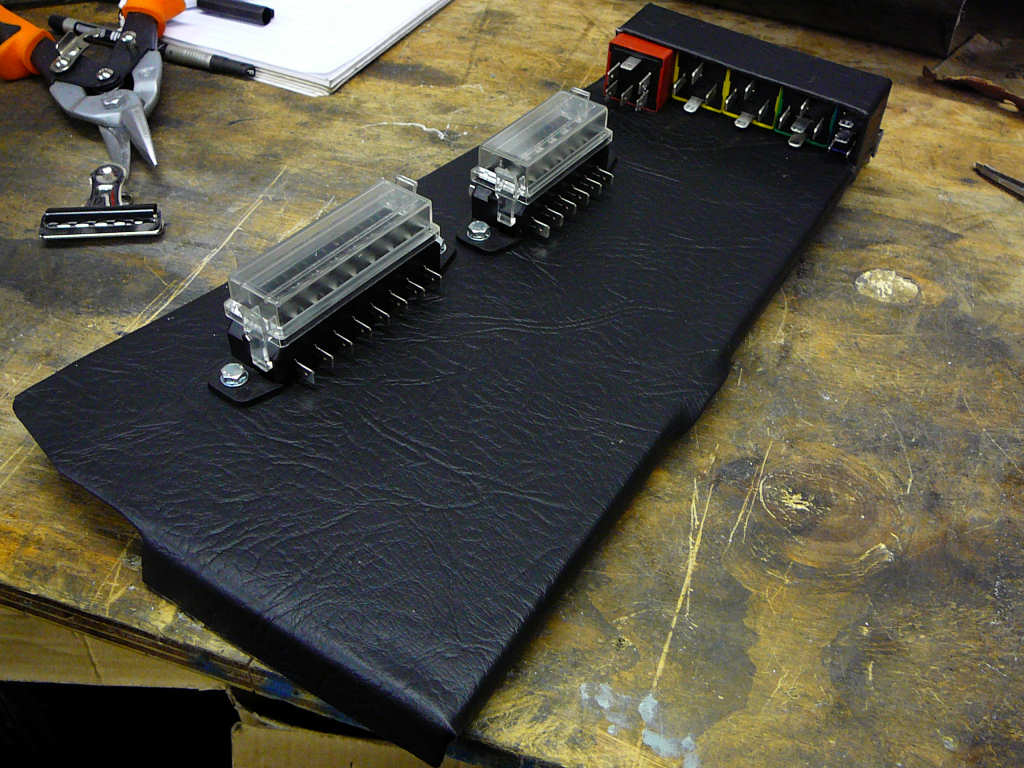
As soon as I had done this, I realised that some holes to feed the wires through would be useful (doh!) so I broke out the hole saw and made the necessary adjustments. The edges of the holes were covered to hide any sharp edges, and the panel was then offered up to the chassis and clamped in place.
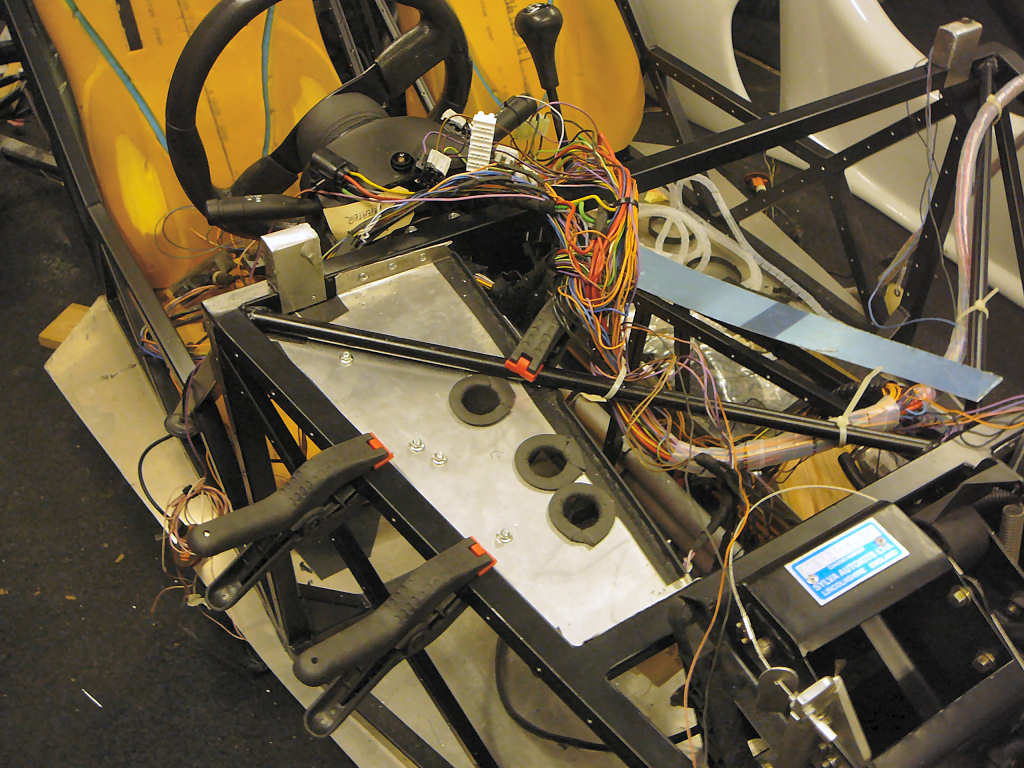
It was then a case of removing each wire from the Fiesta fusebox one-by-one and connecting them to the appropriate place on the new fuse panel. Some time later, it looked like this...
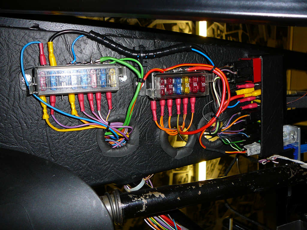
I'll wrap the loom after it has been tested which will make it look a little neater...
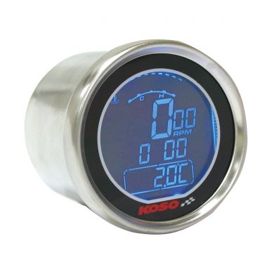
I've also managed to get to grips with the 3D free-air puzzle regarding the dashboard location. The area around the steering column has been cut and reshaped, and the mould-seams have been filled. This is now ready for sanding and then I can bolt it to the dashboard supports. Of couse, I still need to decide on the dashboard layout, but that's still work in progress. I quite like the look of these gauges at the moment, but I'm still deliberating...
There has been a great deal of other things happening in the background such as sourcing the lights, trying to get OBD communications with a spare ECU I got from the scrapyard (1996 Fiesta 1.4 16V), trying to find a Fiat Uno or Fiorino that I can steal the wiper motor from, deciding on a paint colour, working out the best route (or any route for that matter) for the exhaust, sourcing the exhaust parts, finding someone to weld the parts together (it's stainless steel) etc etc.
On the subject of which, these are the part numbers for the various parts for the headlights:
Wipac S5723 - cowl trim.
Wipac S5538 - 5.75" nest.
Wipac LA1016 - UK RHD bulbs (main,dip,side).
And this is what the inside of a eec-v Ford ECU looks like:
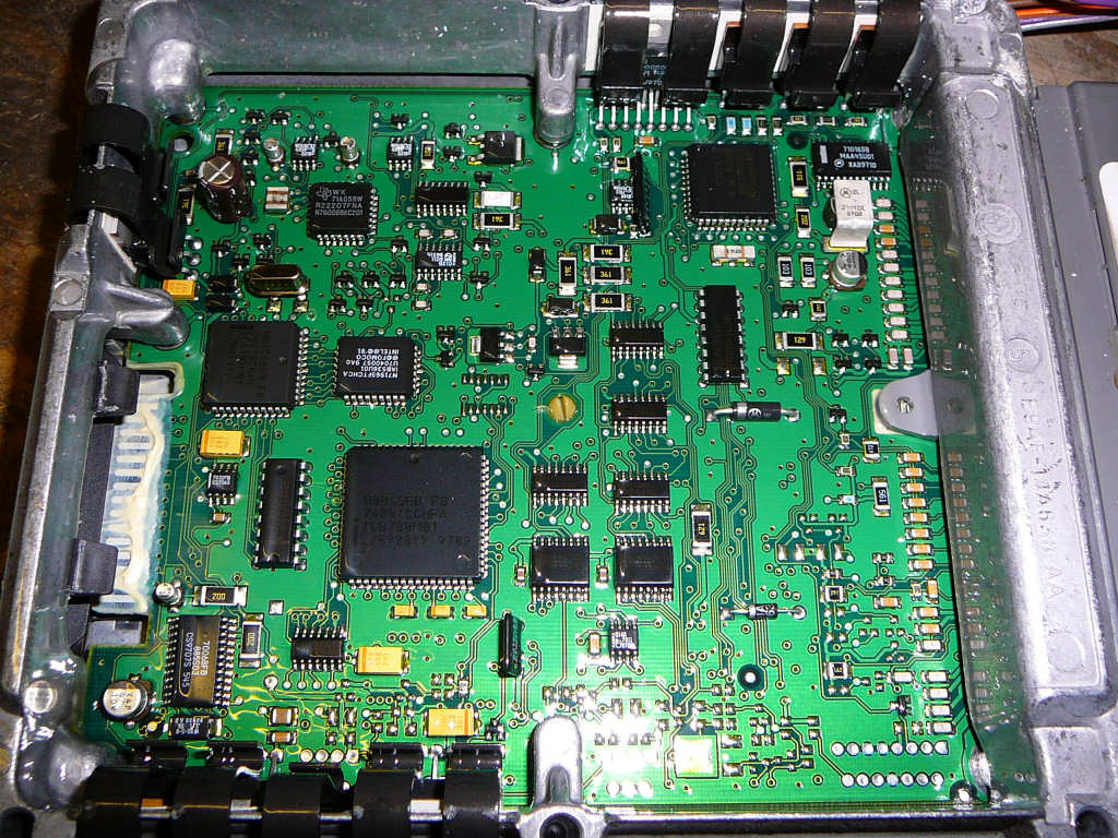
After an evening spent with the wiring diagram from the Haynes manual and a multimeter, i have come to the conclusion that the Haynes manual diagram bears (at best) only a cursory similarity to the actual wiring loom in my car. Some parts are slightly confusing, and some are just plain wrong! I'm currently checking the diagrams from the Ford TIS CD and if these prove any better then I'll put a copy into the resources section.
![]()
Some more parts arrived yesterday - mostly for the heater setup I'm building. The heater matrix is from an old Mini but the fan and associated plastics are just way too big to fit into the Mojo. The plan is to fit the heater box into the space in front of the driver footwell and run hot water pipes through the tunnel. The resulting hot air is ducted over and around the pedal box using 1 3/4" aluminium pipe.
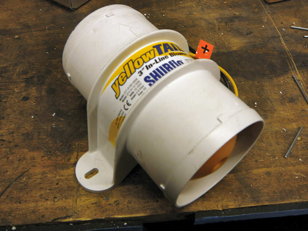
Stage one is to re-house the matrix into a more suitable box, and this box will also house the blower. I've looked at several different blower fans but they all seem a little down on power, or just too big. After much searching (and a pointer from JP) I've ended up using a 3" inline blower that is designed for venting the bilge area in marine applications. The fan is small, powerful and reasonably weatherproof - perfect for this application! This was bought from Salty Sams Nautical Emporium (don't ask) via eBay.
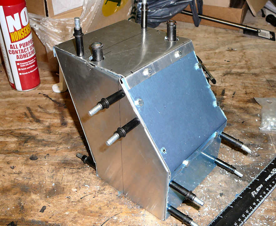
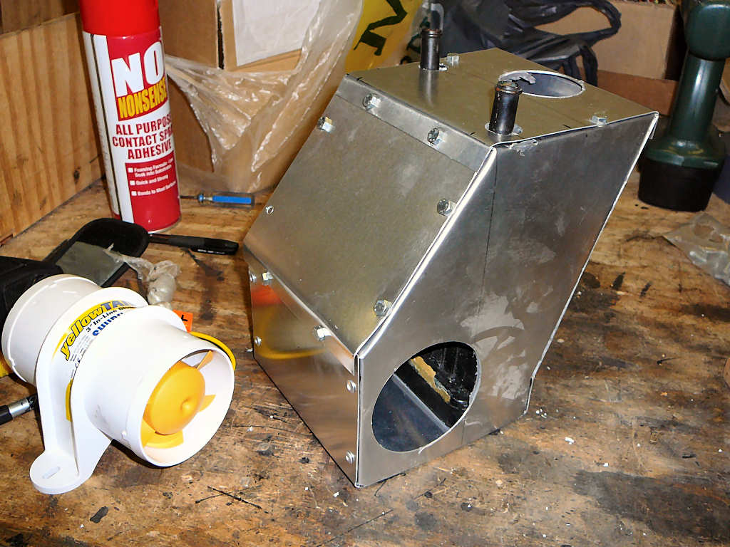
I then started work on the new housing. For this, I made a quick paper template of the shape behind the footwell and then laid the heater matrix onto it. From this, it was relatively simple to come up with a shape that allowed enough space where necessary and should fit into the chassis! The parts were then cut from 1mm aluminium and the edges folded to aid assembly. During mockup, the whole assembly was held together with clekos and rivnuts as can be seen below! Once the basic shape was correct, the holes for the fan and the outlet pipe were cut and checked. The box was finally reassembled with plenty of sealant, rivnuts, bolts and rivets.
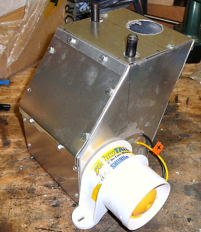
Once everything has dried, I'll cover the joins with duct-tape (finally using the stuff for it's intended application!) and fit the box to the chassis. The next stage will then be running the pipes and working out what to do at the other end of the hot air pipe.
I've also uploaded some wiring diagrams to the resources page - these are taken from the Ford TIS CD and are somewhat more accurate than the offering from Haynes.
![]()
A few odd jobs were done this weekend: Firstly, the seats have been covered.
They're not quite up to professional standard with regards to wrinkles etc, but they are suprisingly comfortable and look the part. They'll certainly do until I can afford to replace them! The seat covers came from Argos and didn't need the anticipated cutting to make them fit the modified Mojo seats. A liberal coating with spray contact adhesive ensures that they should stay where they are for a while.
I also mounted the exhaust. To do this, I needed to make a pair of brackets that fit onto the lower suspension bolts.
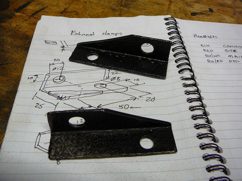
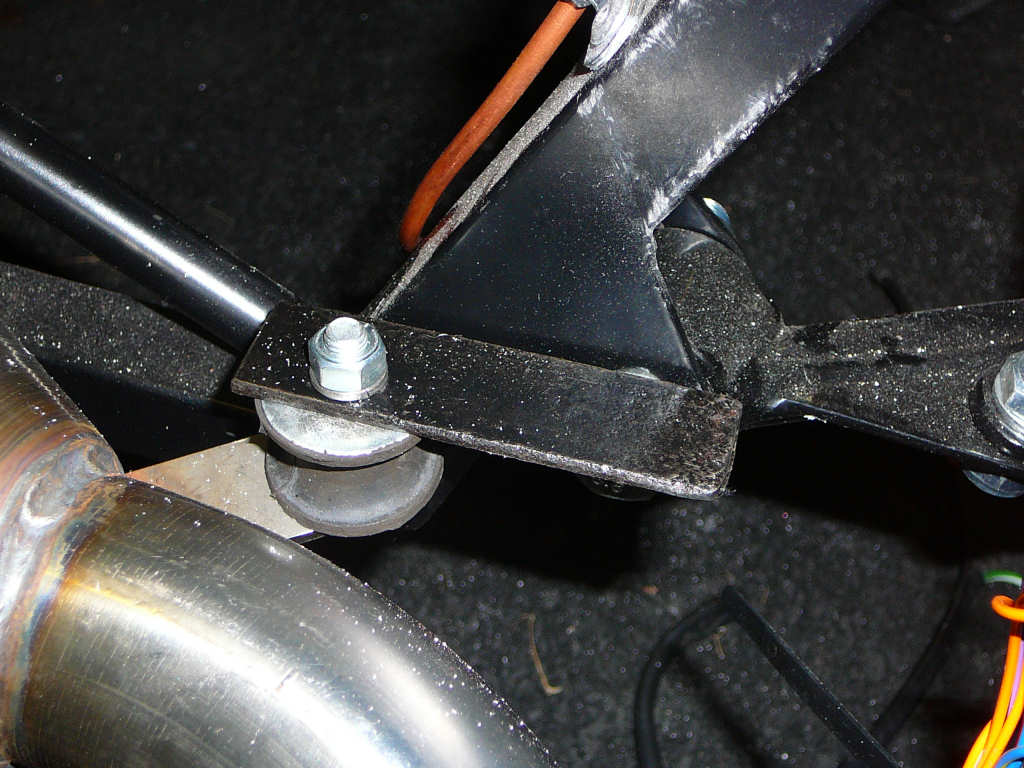
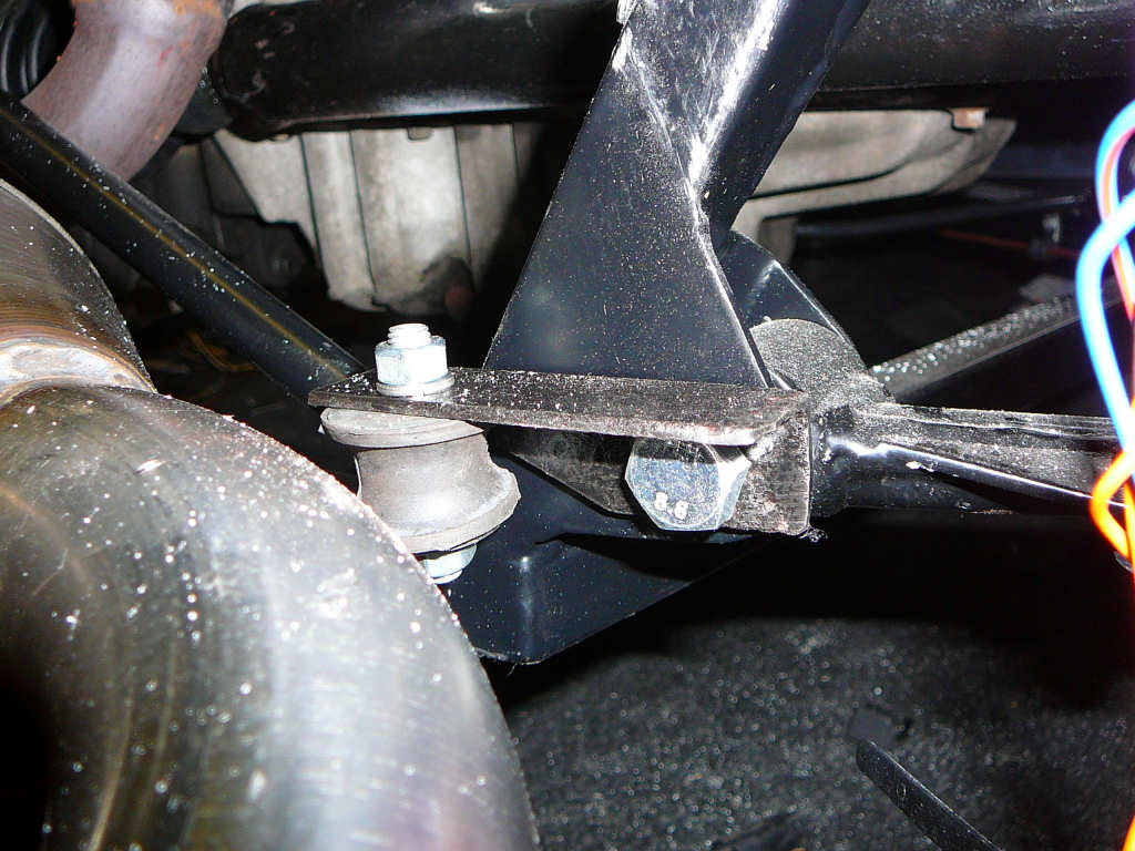
These are really simple brackets made from 25mm x 25mm angle iron that was cut, drilled and painted with a coat of hammerite.
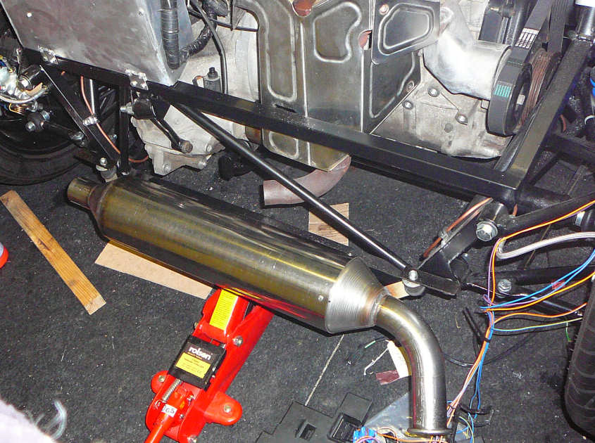
The can is quite heavy and will require some extra support since the rubber mounts are quite soft and flex considerably under the weight! I'll browse some build diaries to see what others have done in this respect...
More work has been done to the cockpit heater box that will act as a plenum between the heater hose, the demist vents and the footwell vents. The dash vents are from an Alfa Spyder and I'm still trying to source some suitable footwell vents. As with most things on the Mojo, they need to be smaller than anticipated as there isn't much room! I'm still trying to find the Uno/Fiorino wiper motor so I can check clearances before continuing with this. Photos to follow...
The final job I undertook this weekend was to fit the headlights. The light units themselves are standard Wipac parts from SVC and come complete with the plastic backshell, bulbs and wiring. I've gone for the H4 bulbs (55/60W) with a sidelight since the Fiesta wiring loom is set up this way.
In order to fit the lights, the fibreglass bonnet needs to be marked out and cut. On the headlights, there is a small arrow which must be pointing striaght up after fitting. With this in mind, it was a relatively simple job to mark out the desired cut (using the headlamp gasket as a template) and chain-drill the aperture. This was then sanded smooth using a flap sanding wheel. I also had the workshop hoover running with the nozzle right next to the work area to try and remove as much of the dust as possible!
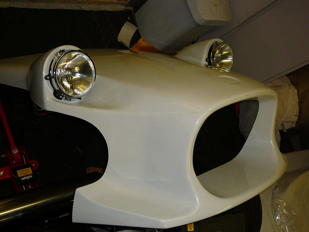
The Mojo uses the optional Wipac headlight cowl to blend the headlights to the bodywork. I was lucky enough to get these donated from 'moospeed' (aka Steve) on the Sylva Chatlist. Thanks Steve!