

![]()
Sorry about the lack of updates.. here's a bit of a mammoth one for you though. Hope you're sitting comfortably?
Over the Christmas break, I was lucky enough to have a fair amount of time out in the workshop and have consequently got a decent amount done. Being sub-zero temperatures for much of the time hasn't helped, but it's amazing how quickly you warm up when sanding bodywork!
The last installment culminated in the headlights being fitted. I've since gone on to mount most of the other lights with the exception of the side indicator repeaters as I still haven't ordered them (The Fiesta side repeaters are too 'deep' to fit behind the bodywork so I'll go for some low profile LED ones soon..).
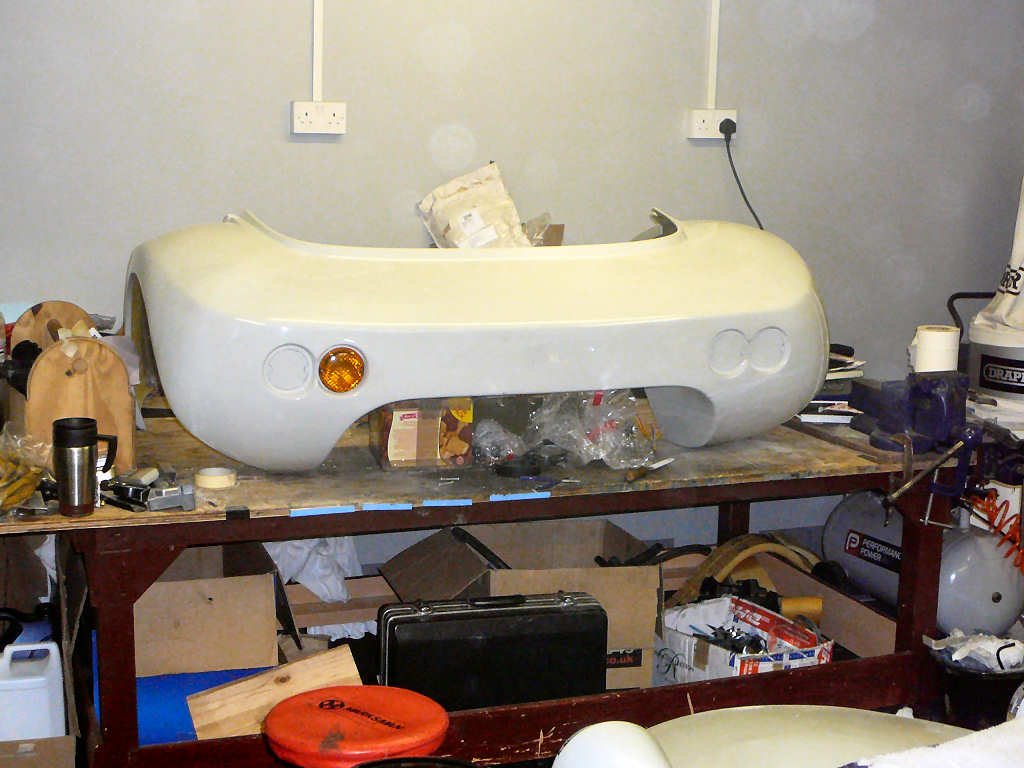
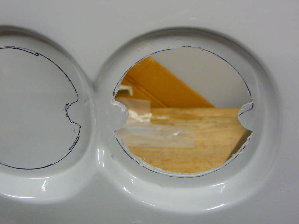
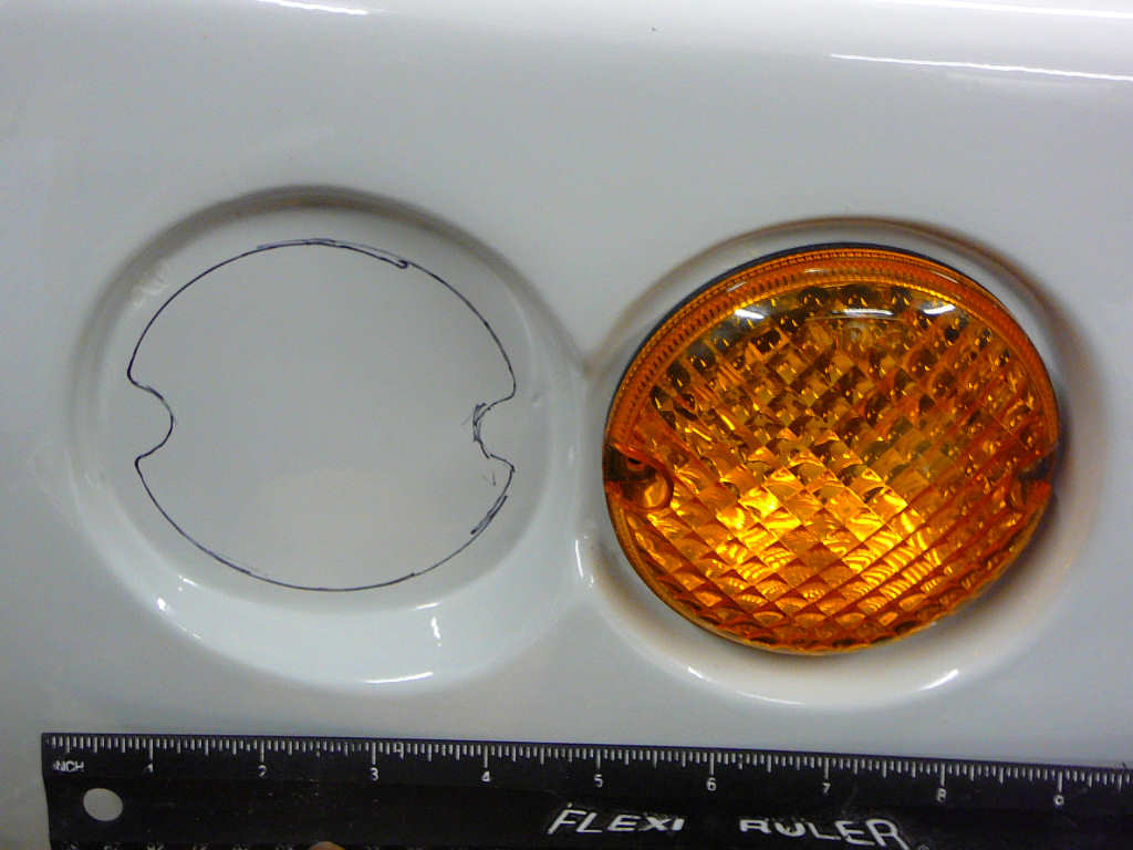
First job - fit the rear lights. This was a case of using the black bezels to mark out the cut lines, then chain-drill and sand smooth. I used a rotary sanding drum in my drill to do the bulk of the sanding which resulted in a fair amount of dust but gave a nice result and didn't take too long. It certainly helps having a large bench to do this job on! The lights are NAS units from Wipac, and I got all 4 from eBay for just £12 including bulbs.
I then moved on to fitting the front indicators. This required fitting the cycle wings which I've been dreading for some reason. In the end it was a relatively simple procedure in which I bent the wing stays around to even up both sides, and then cut recesses in the wings to clear them. In order to fix the wings on, I wanted to use something like a bighead fastener and bond it to the underside of the wing using fibreglass mat and resin. Unfortunately, I didn't have any bigheads, so I ended up making something similar. To do this, I got hold of a few large (40mm) fixings that are used to retain cavity wall insulation and then formed them over the heads of some M6 bolts using brute force and ignorance. I'm wishing I took some photos of these now because its hard to describe and a photo would really help. Oh well.. Once these were ready, I drilled 8 holes in the wing stays and dropped the big bolts in loose. I put a dab of Tigerseal on the head of each bolt and the lowered the cycle wing into position. Once this had dried, I carefully lifted the wing off, turned it upside down and fibreglassed the bolts in place. When I read Neil Everett's build diary, he came across a slight problem when removing the wings since the bolts naturally point towards each other making it impossible to lift the wing off straight. In readiness for this, I made the holes in the forward most wing stays into slots which cures the problem. I'll use some largish washers during the final fit to ensure that the wings stay where they're meant to!
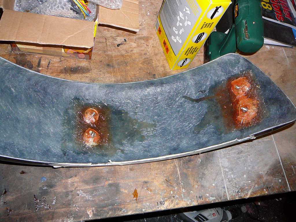
One thing to say about doing this kind of fibreglass work - it's not difficult (in fact it's quite easy) but it can get very messy! Be prepared to get resin everywhere!
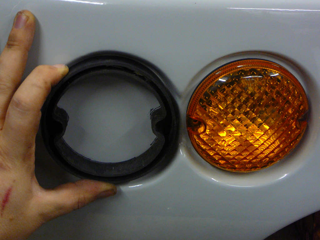
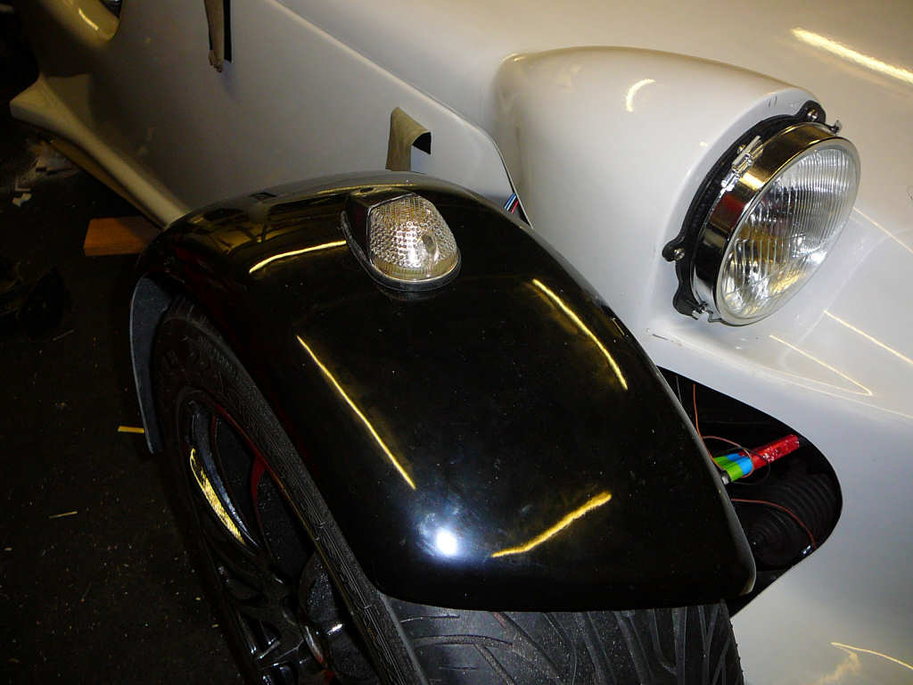
I left the fibreglass to set overnight, then added a second layer. This was left for another night to harden and then I fitted the front indicators. A simple matter of measure, make, drill, and fit. The indicators I'm using came from S-V-C and have a metal base, carbon effect housing, and a clear lens. This was bent to fit the contour of the wing and the top plastic was filed to match, which should help them to sit flat and level. The bulbs fitted are coloured, but they look a little yellow to me. The SVA/IVA manuals state that these indicators must be 'the correct colour', and this is only ever identified as 'amber'. I think I'll get some other bulbs just in case.
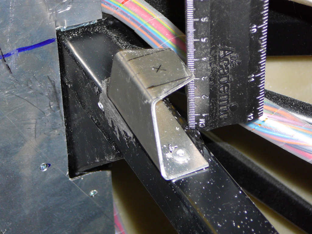
I've also finished the plumbing of the heater matrix. I've plumbed some 15mm pipe into the heater circuit of the engine coolant system and connected this to the original Fiesta heater valve. This valve is electronically operated and either allows hot water to flow through the heater matrix, or bypasses the matrix and returns the water directly back to the engine. The heater valve is just a simple 12V solenoid and I'll need to make up some electronics to drive it but I'll do that later. The heater valve is supported on a bracket and is located at the front of the tunnel. I think I'll have to put some sort of inspection hatch in the passenger footwell just in case I ever need to get to it again.
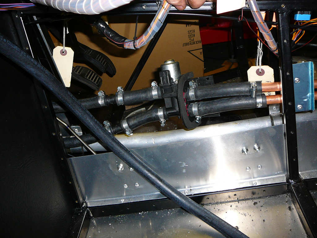
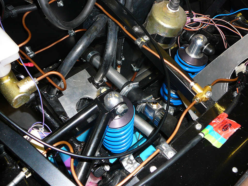
You may also just be able to make out the new coolant temperature sender in the right hand photo above. This sender comes with my new Koso speedo and tacho mentioned previously so it needed to be installed somewhere suitable. I got a 32mm adaptor from Car Builder Solutions which fitted perfectly (the sender is a standard M10 thread, and so is the adaptor). I've since mounted the heater box down to the chassis using a bracket but this isn't shown above unfortunately. I've refilled the coolant system and bled the matrix and there's no leaks so far which bodes well.
Whilst mucking around in the tunnel, I've fitted the handbrake switch. I've reused one of the door switches from the Fiesta for this since they're robust and easy to mount.
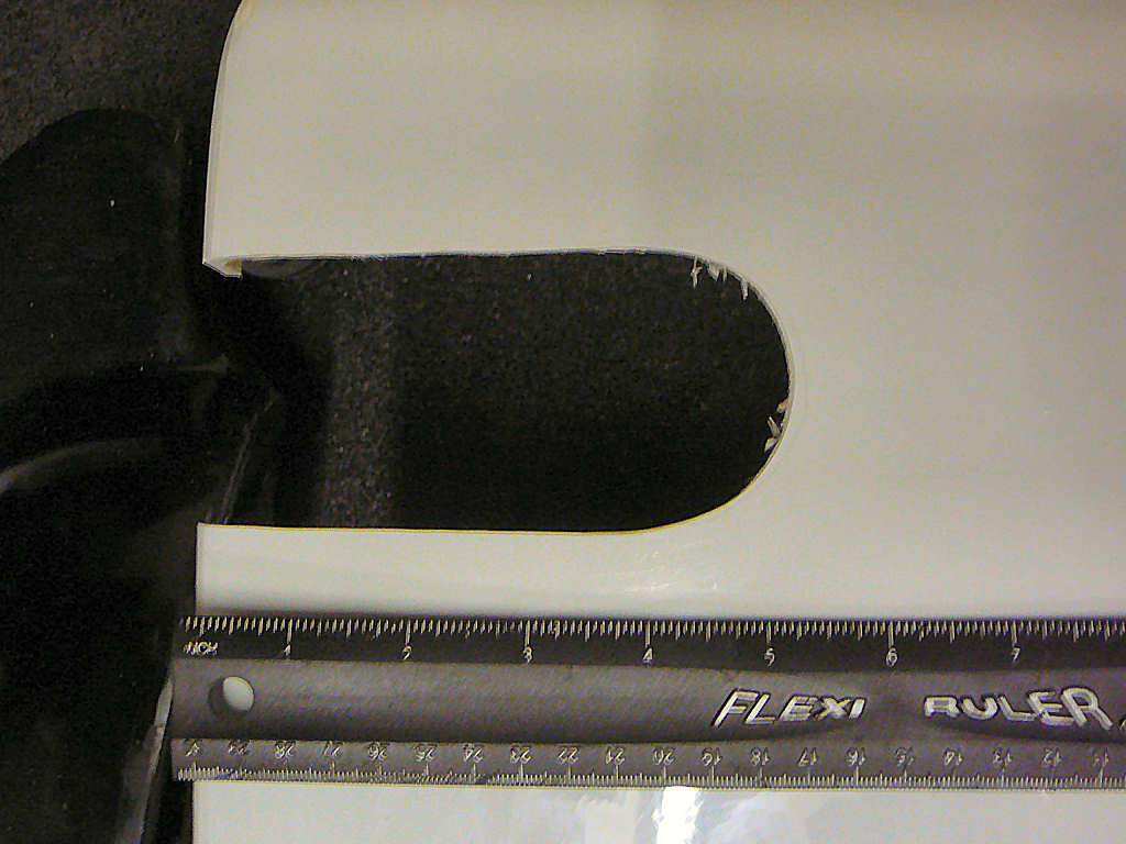
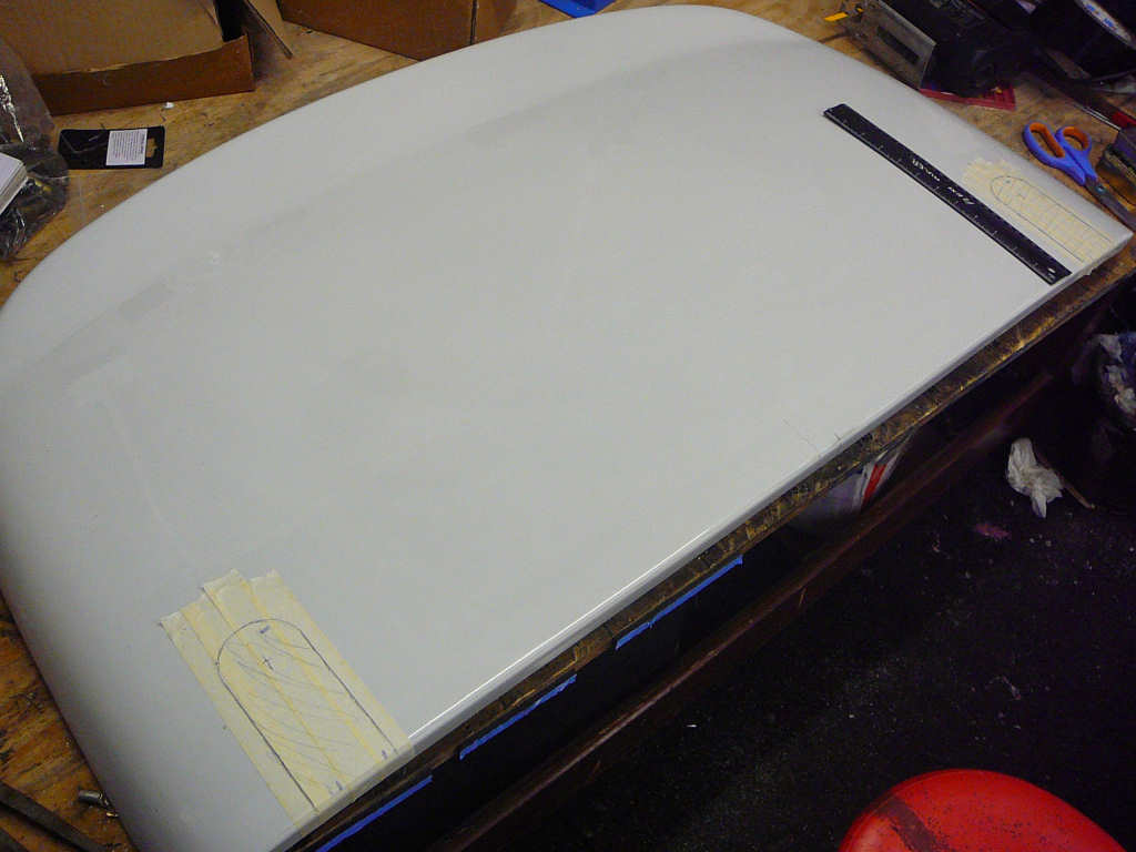
Back to bodywork for a while: I measured, marked, and then cutout the engine cover to allow it to fit around the rollbar. Although not difficult, this was a bit of a test of confidence since there is almost nothing to reference any measurement from! i ended up using a large sheet of cardboard and trimming it away until I had a suitable template. Once I was happy with this, I used it to transfer the marks to the fibreglass and got cutting. Fortunately, the hard work was worth it and it fits perfectly! Phew.
I've also fitted the bonnet hinges. This was a simple job that only took a few moments. These are held on with M8 nuts and bolts with some larger washers to help spread the load and prevent cracking of the fibreglass.
As you can see, I've used some small jubilee clips to stop the hinges moving from side to side along the bar. I've ordered some flush bonnet locks from Rally Design which should turn up soon.
I've started fitting the rear bodywork which is more of a struggle for several reasons. It's on hold for the moment until i can set the rear ride height correctly, and I'm waiting for a C spanner from Rally Design before I can do this. I guess the 140mm measurement mentioned in the build manual is from the rear chassis cross member near the exhaust?
For now, this is how far I've got. It all sort of lines up, but it still needs some fettling.
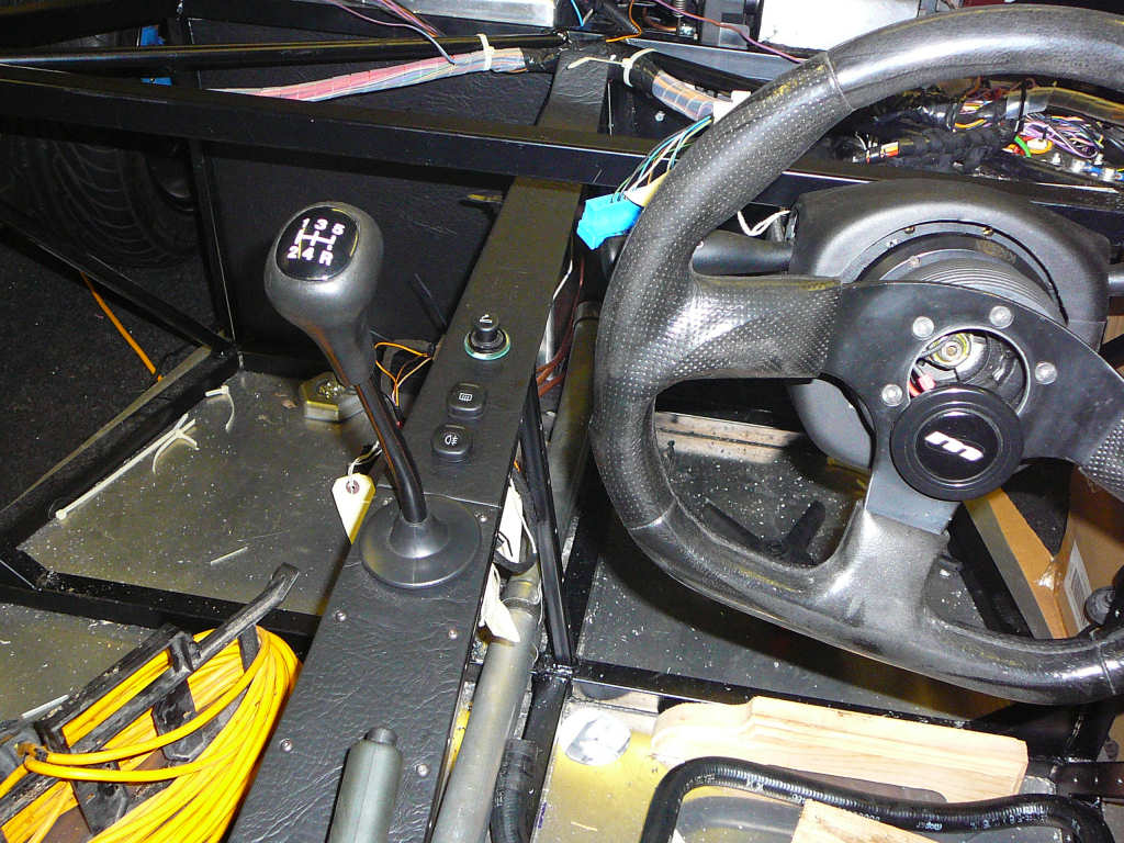
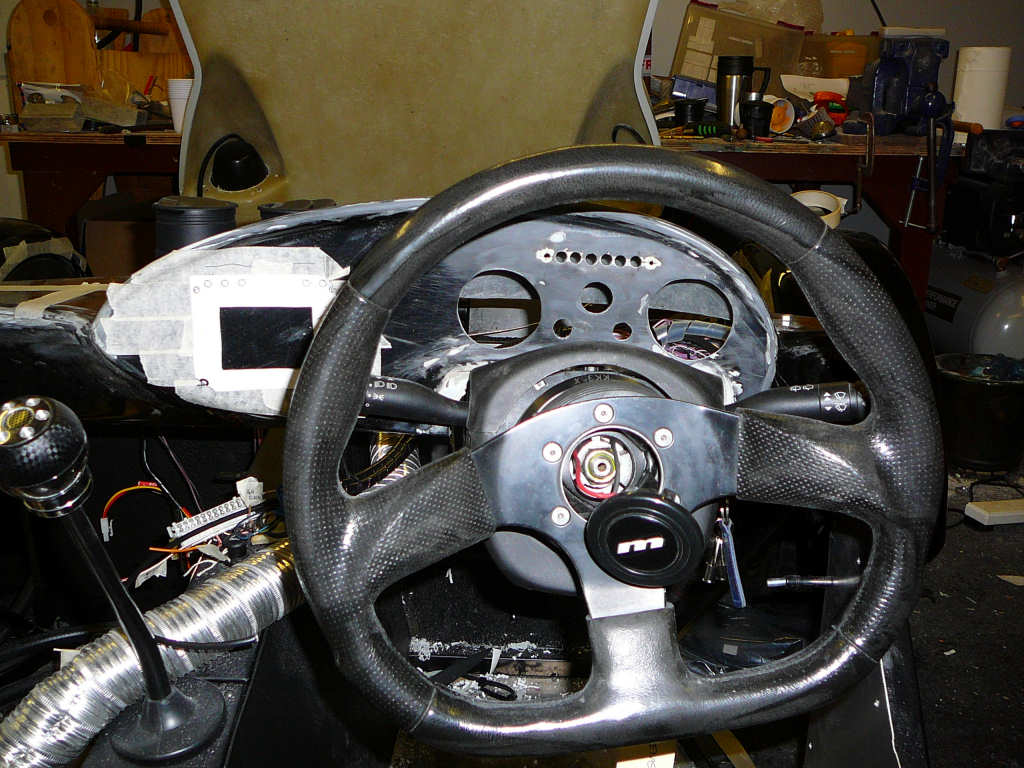
I've also fitted a simple bracket to hold up the bottom of the cowling around the steering column as this was getting a bit floppy since I've cut most of it away!
And I've finally got round to fitting the switches and power socket into the final cover for the top of the tunnel.
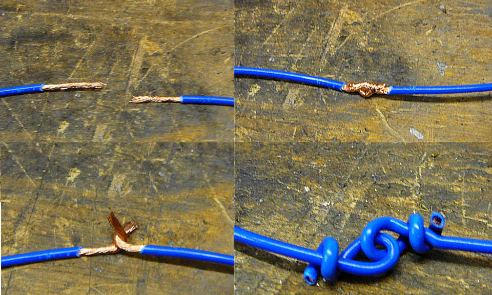
The rest of the time has been mostly taken up with wiring. In several places I've needed to extend the wiring loom and in others, I've needed to shorten it. In order to make sure that the wiring does not fail, I've always used a robust method of joining the wires. Firstly, the wires are folded over each other as a hook joint, and then the tails are wrapped back around themselves. When soldered, this results in a joint that is mechanically strong and should survive the harsh automotive environment.
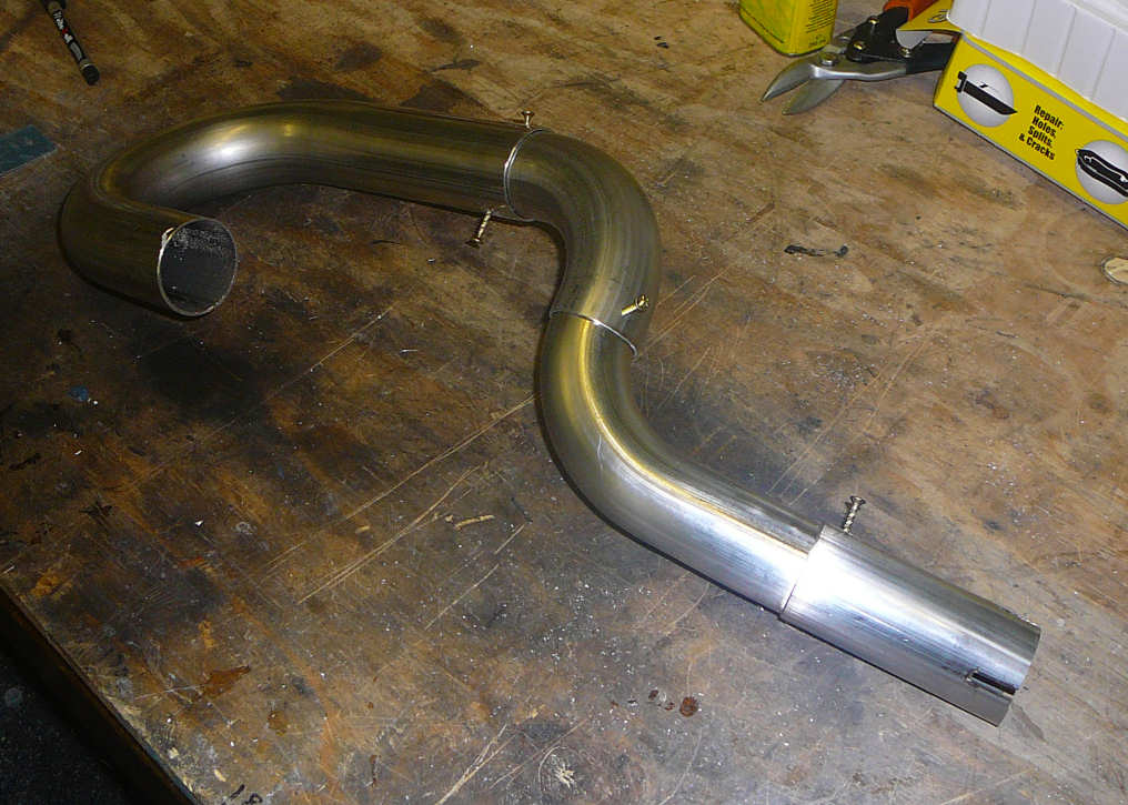
Finally, I've ordered some stainless steel mandrel bend pipes from OJZ Engineering to make the exhaust. These should arrive tomorrow along with the wiper motor and arm from a Fiat Florin (which is the same as a Fiat Uno apparently.) The exhaust parts I've ordered are:
- 90 degree stainless steel 1 3/4"OD bend (150mm legs)
- 90 degree stainless steel 1 7/8"OD bend (150mm legs)
- 180 degree stainless steel 2"OD J bend (150/250mm legs)
The reason for the odd sizes is twofold. Firstly, the silencer needs a 2"OD pipe to fit, and the Fiesta cat has a 42mmOD pipe coming from it. Secondly, The 1 3/4" bend should fit snugly over the Fiesta pipe, the 1 7/8" pipe fits snugly over the 1 3/4", and the 2" fit snugly over the 1 7/8". This means that assembly will be made slightly easier as I can slip the pieces together until the correct fit is achieved. I can then drill and rivet them to hold them in place for the trip to the welders. Once the seams have been welded, the rivets can be drilled out and the holes filled with weld. Hopefully this will reduce and accidental movement of the assembly and ensure that the exhaust will still fit when I get it back. However,I'll probably have to remake to exhaust mounts because I think I'll need a bit more space behind the silencer to fit the pipes.
![]()
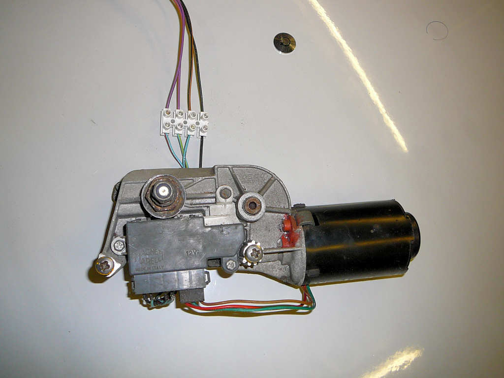
Well, all the bits did turn up as expected. I'll get around to the bonnet locks and ride height over the weekend, but I made a start by looking at the wiper motor. As mentioned, this is the wiper from a Fiat Fiorino van.
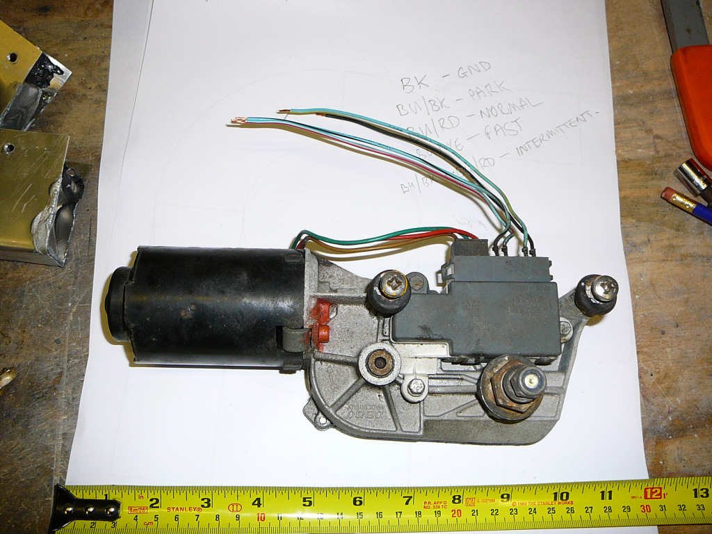
I've had a preliminary stab at working out the connections, and now I need to work out how to interface this with the Fiesta wiring. I also need to locate a shorter arm and suitable wiper blade so it looks like it'll be another trip to the scrapyard this weekend...
I also started looking at the exhaust components.
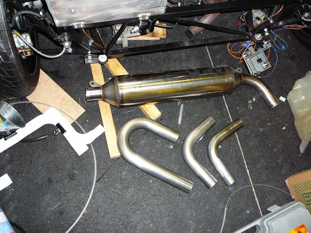
As expected, I've had to move the silencer back a couple of inches to make room for the pipe from the bottom of the catalytic converter. I've done this by making a couple of simple brackets that bolt to the mounts I made before. I'll get these welded up in due course.
The 1 3/4" bend was supposed to be a slip fit over the Fiesta exhaust but this didn't work out in the end. The Fiesta pipe is not particularly circular and has all sorts of ripples and lumps in it. After much filing and bending, I ended up being able to get about 20mm of joint area between the two which isn't really enough for my book. What I've decided to do is to use a bit of the off cut of the 1 7/8" pipe as a sleeve to reinforce the joint. I'll put some slits into this and secure it with a band clamp.
The other parts all fitted together well, and it was a simple case of offering the parts up, marking the cut line, and cutting to length with a hacksaw. With a bit of deburring and one cut finger, all the parts are in place.
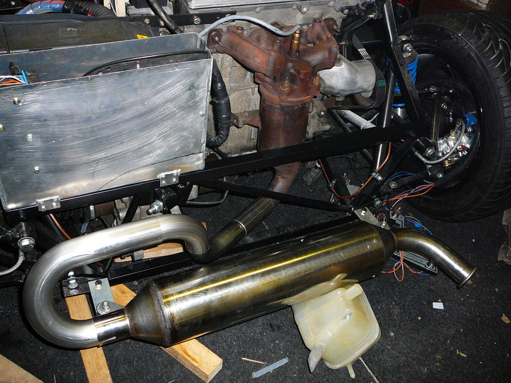
I'm quite happy with the result so far, but I've refrained from fixing them permanently just yet. I think I'd like to move the silencer back towards the chassis a little more just so it doesn't hang out the back of the bodywork too much - I need to check this. That'll be the job for the weekend then!?
![]()
Well, I've checked the exhaust position and it looks fine to me so the next step is to fix the parts of the exhaust together and tack them in place ready for welding.
As you can see, all I've done here is drill holes through the sidewalls of the exhaust and secured the parts together using some wood screws. It's not the proper way to do it, and there are probably better ways but it seems pretty secure and should survive the trip to the welder. You can also see the 1 7/8 sleeve mentioned above that helps secure the exhaust to the Fiesta down pipe. I've cut some slits into it to help the band clamp hold it in place eventually.
I've struck lucky with the welding and my wife has managed to persuade one of her work colleagues to do the welding for me. Without saying too much, he normally welds parts for some rather specialised military aviation so you know the quality of welding will be ok for a kit car exhaust! So, camouflaged in several carrier bags, the exhaust went into the wife's car, and came back like this..
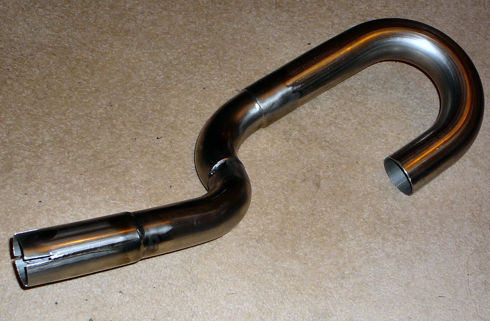
The screw idea really did work well as there appears to be little or no distortion evident that you normally get when welding - indeed you can't even tell where the screws used to be! The welding here really is superb - thanks Ben!
Of course the acid test is to see if it still fits onto the car - and it does. I just need to locate a 48mm band clamp now and I'll be able to fit it permanently into place. I've also spent some time modifying the bodywork around the exhaust to make sure there's enough clearance - photos to follow.
I've been speaking to Matt Beardshaw who is the new owner of the Mojo project - http://www.meggt.com. He's been battling with the electrics of the blue Mojo that Jeremy Philips was building just before selling the project, and there are some problems with the wiring. Anyway, he's now gone and bought another Fiesta to compare against so hopefully it'll be up and running soon! Good luck Matt!
Finally, I had an email from Neil Everett earlier today (thanks Neil!) that has cleared up a problem I was having regarding the ride heights. The manual states that the ride height should be 140mm at the rear and 120mm at the front, and these are measurements from ground level to the bottom of the chassis rails. Unfortunately, there was absolutely no way I could get either of these settings out of my suspension - I simply ran out of rebound travel in all cases. It all looked fine until you jumped up and down on the chassis and then you could easily hear the shocks hitting their end stops. "That'll be a handful on the road" I thought to myself!
Well, I eventually managed to get around 100mm at the front and 120mm at the rear. In his email, Neil has stated that he's currently running 100mm at the front and 110mm at the rear. Since Neil's car has been on the road for some time, and there are no reported problems, then I'm a lot more confident and happier with the setup I've got. I still need to do the corner weights, but this'll have to wait until I can get to a garage. Phew.
Next stop - finish the wiring and start the engine!
![]()
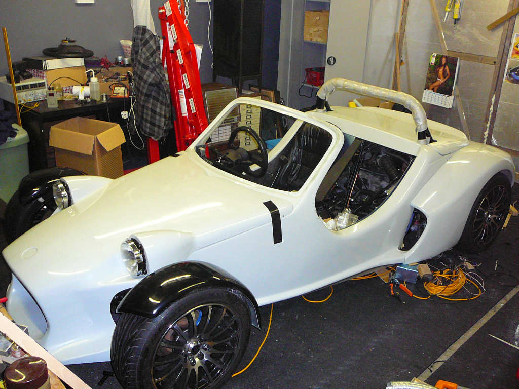
Well, a major milestone has been reached. Here's the story:
I had set a goal for this weekend to get the engine running. In order to do this, I temporarily connected the last few bits such as the fuel pump etc and with some trepidation I turned the key for the first time. This resulted in the fuel pump priming as expected, but the starter motor just did not turn. I checked the fuses, the earths, and the relays and found that the earth to the starter relay went to the ECU which got me thinking... As a test, I plugged the Fiesta clock back into the loom as this has an LED in it that may give a hint to the fault. When I turned the key, the LED was flashing like crazy! One strong cup of coffee and an moment of enlightenment later, I took the cowl off of the steering column and plugged the immobiliser transceiver back in... nuff said! By now, it was getting on towards 1am which explains a lot and I decided not to try and start the engine just yet in case it made as much noise as I expected! I couldn't resist giving the key a quick flick however, and the starter motor clicked into life for a fraction of a second. This proved that the immobiliser problem had been solved, and I could sleep easy.
One very long Monday later and a day behind my self imposed schedule, I finally made it back from work and headed straight out to the workshop. I made a quick double check of last night's efforts to make certain that I hadn't missed out any other blindingly obvious things, and turned the key. Nothing happened. I went to the back of the car, turned on the battery isolator, made an appropriate offering to the gods of profanity, and went back and turned the key again. This is what happened...
I particularly like the moment where the engine starts for the first time, and the front cycle wing falls off in sympathy. I must remember to get around to bolting them on. The warning lights on the dash are for the airbag system (which went in the bin) and the battery voltage. The battery I am using has been sitting for some time now and will really benefit from a round of desulphation and a good solid charge - so much so that I had to use the old Fiesta battery to help jump start the engine tonight!
As many other builders have mentioned in their diaries, it can't be overestimated how great it is to finally hear your engine start after so long bolting parts on, making brackets, and scratching your head. It really is a wonderful moment when the pile of parts and wires in front of you stops being mostly old Fiesta, and suddenly becomes mostly new Mojo.
I think I'll go and celebrate by ordering some more parts...

![]()
Well, the euphoria of getting the engine running has slowly diminished to a wry grin and I've turned my attention back to the seemingly endless list of jobs that still need doing.
As mentioned, I've just ordered some new parts to fit, some of which have worked out better than others. The main part I've had problems with are the side mirrors. I ordered a pair of the 'small carbon' mirrors from Car Builder Solutions but these have turned out to be a bit too small, have no E marking, and will not conform to the SVA test in which they need to fold when a 10Kg force is applied to them. CBS do list a more appropriate set which I'll swap these for this week.
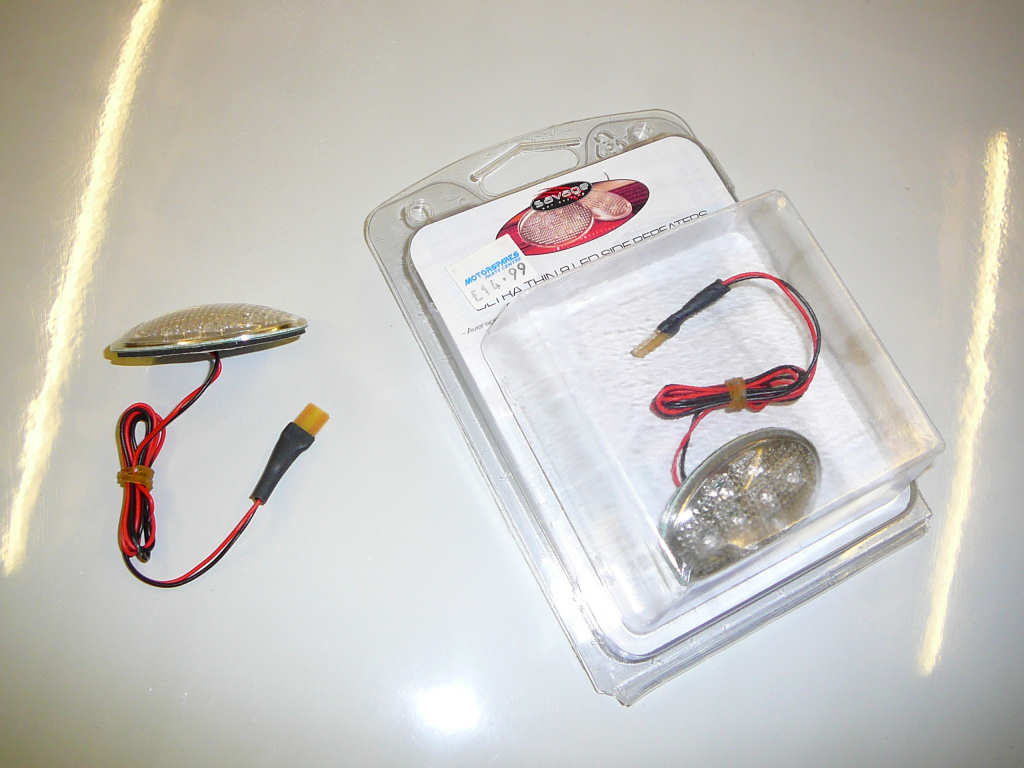
I found a set of side repeaters at the local boy-racer store which will fit the Mojo nicely. They're clear lensed, LED and very low profile so it'll be much easier to find a place to locate them on the bodywork. I'll mount these this week.
Other new parts are mostly to do with wiring, so loads of connectors and convoluted tubing is now in! On the subject of which, wiring has taken up much of the recent workshop time, and fettling the dashboard has taken up the rest.
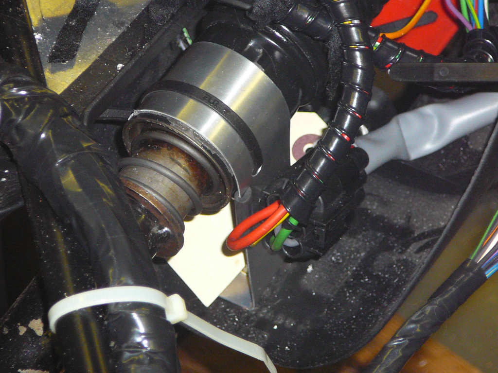
With regard to the wiring, this is now 80% complete and I just need to finish off the headlights, rear lights and dashboard before I can declare this job done. Whilst checking the on-board-diagnostics with the laptop the other night, I noticed that the OBD port is permanently live and not switched by the ignition. Therefore, one of the first jobs on the wiring list was to rewire the diagnostics connector so that it is only powered when the ignition is on since I eventually want to use the diagnostics port in conjunction with a touch-screen display on the dashboard. In the end, this was a simple matter of swapping the feed to the connector from one fusebox to the other.
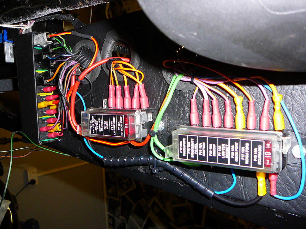
The fusebox on the left is mainly fed by permanent +12V whereas the fusebox on the right is mostly fed by switched +12V. This makes it really easy to do this kind of modification!
You may also notice another subtle change to the fusebox which is the new green relay in the background. This has replaced the Ford 'wiper motor' relay to allow me to interface the Uno wiper motor to the Ford switchgear. The Uno wiper I have got has 4 wires coming from it:
- Black - Ground
- Blue/Black - connect to +12V to park.
- Blue/Red - connect to +12V for standard wipe
- Blue/Yellow - connect to +12V for fast wipe.
Also, if you connect +12V to Blue/Black and Blue/Red at the same time then the motor operates in 'intermittent' mode. The wiper motor has got 5 connections and the missing wire from my motor is normally a plain blue wire. Apparently, this gives the 'standard wipe' connection when connected to +12V which is the same as the Blue/Red wire on my motor. Maybe my motor is dodgy, I don't know - but it works so I'm happy.
Of course, the Ford switchgear is utterly incompatible with the simple switching required by the Uno motor, hence the need for the new green relay. The function of this relay can be summarized as 'Connect Blue/Black to +12V unless Blue/Red or Blue/Yellow is connected to +12V'. This gives the auto park function. In order to get the intermittent function working, the Ford switchgear is wired to connect Blue/Black to +12V when in the 'intermittent' position. It's probably about time I stopped trying to describe it and showed a diagram! I've collated all of my notes from my workshop notebook including this diagram to a PDF file in the resources section - click the image below to go there now...
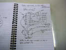
This took some time to decipher the various Haynes and Ford diagrams to get the switch wiring, and then to work out a solution. The good news is that it works perfectly! It should also be relatively simple to use toggle switches or a rotary switch instead if preferred.
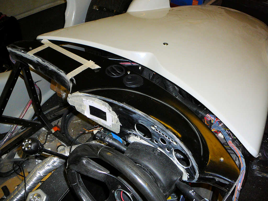
The dashboard has also been keeping me busy. I've spent quite some time sitting in the car with a roll of masking tape and a pen marking out various layouts for the gauges and I've ended up with this.
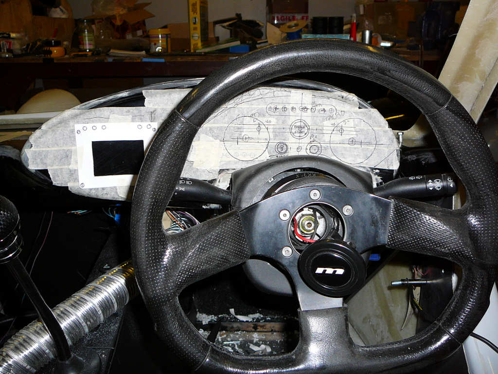
From left to right, the black square is where the touchscreen controller is going to fit, then the speedo, and the tacho on the right. The bright-6 display fits across the top of the gauges, and there's space for a 'sidelight' indicator, a trip/ODO reset switch, and a large 'engine start' switch in the middle. The next job was to drill the holes which was taken very carefully! There were a couple of marks on the dashboard face so these were filled with filler and sanded down to give a smooth surface for painting later. I got hold of some wrinkle paint to do this with, but it needs to be done at a temperature of 25 degrees which we're unlikely to see for some time! I may need to rethink this...
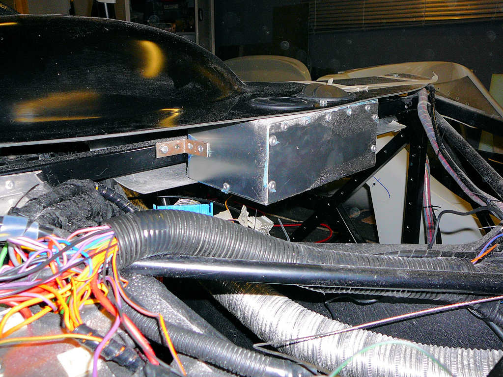
After the holes were drilled, I finalized the dashboard mounts and fitted the vent box into position. The vent box acts as a plenum chamber for the heater and the demister vents mount directly to it through the top of the dashboard. Everything was bolted together, and the holes for the vents were drilled using a hole saw. I still need to drill the hole to fit the flexible aluminium ducting into, nut I need to check clearance around the wiper motor first. The vents I am using come from an Alfa Romeo, and I actually found a spare pair of these of Saturday down at the scrapyard! I may use these for footwell vents, but I'm still thinking this though.
Also at the scrapyard I got the relay for the wiper modification, and the rear wiper arm from a Fiat Stilo. This is a nice rounded plastic affair so it should be great for SVA!
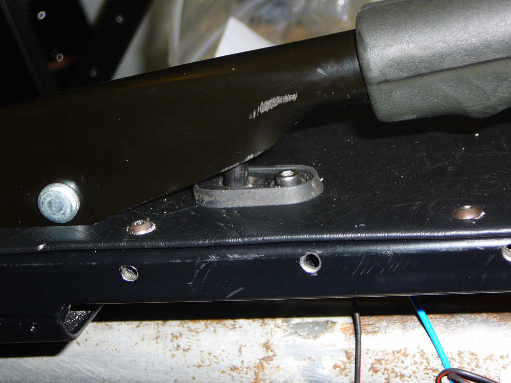
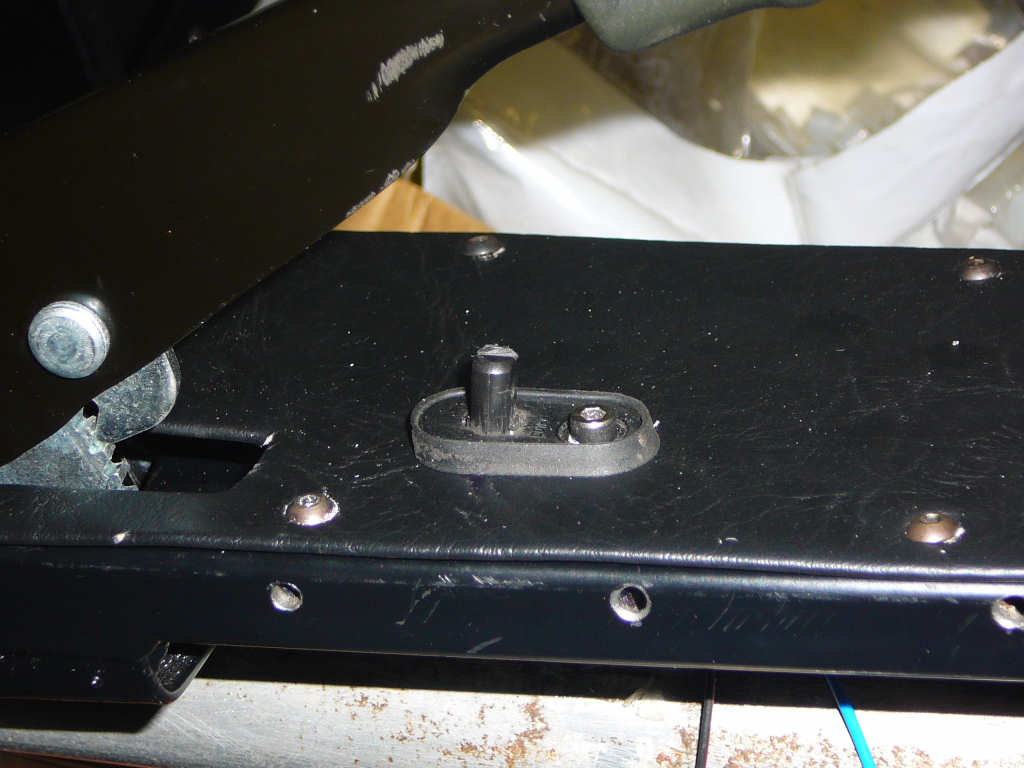
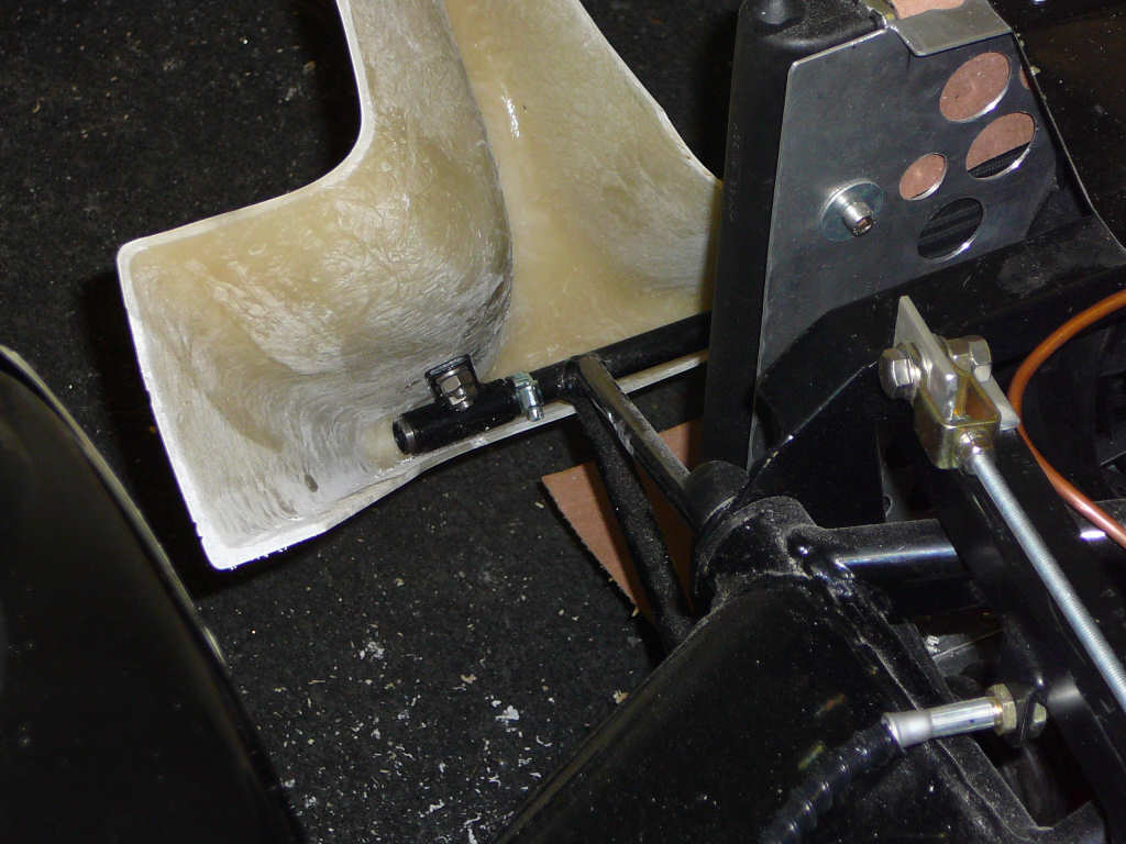
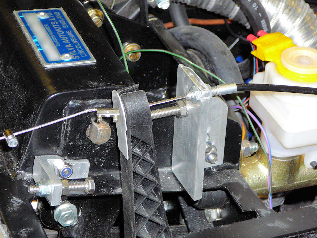
Other jobs I've managed to get done are the fitting of the bonnet lock, and the limits for the accelerator pedal. The bonnet lock required a simple folded bracket and drilling a hole in the bonnet.
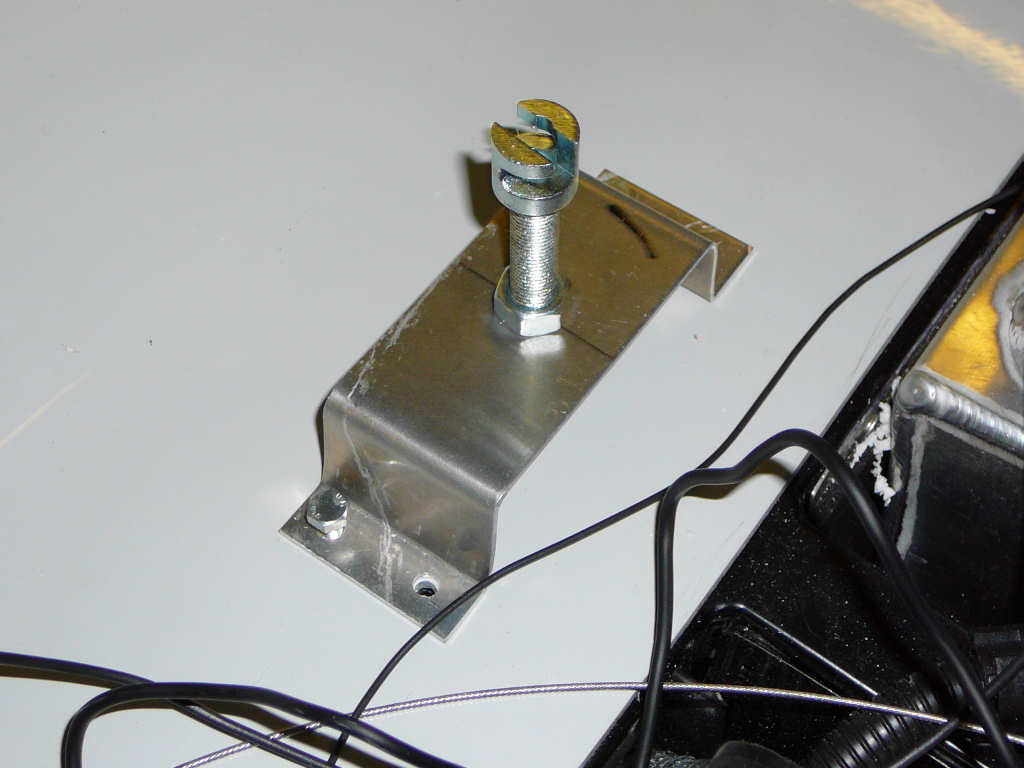
And the limits for the accelerator pedal are to stop excess strain being put onto the throttle cable.
So, the jobs go on but each one that goes by means I'm one step closer to booking my SVA... shouldn't be long now!
![]()